RL78/G15 CHAPTER 11 COMPARATOR
R01UH0959EJ0110 Rev.1.10 Page 357 of 765
Mar 7, 2023
11.4 Comparator n Operation (n = 0, 1)
The CnMON bit in the COMPMDR register is set to 1 when the analog input voltage on the IVCMPn (n = 0, 1) pin is
higher than the reference voltage. When lower, the CnMON bit is set to 0.
When using the comparator detection n interrupt (INTCMPn), set the CnIE bit in the COMPOCR register to 1 (interrupt
request enabled). If the comparison result changes at this time, a comparator n interrupt request signal is generated. For
details on the comparator 0 interrupt, refer to 11.4.2 Comparator n Interrupt Operation (n = 0, 1).
Remark n = 0, 1
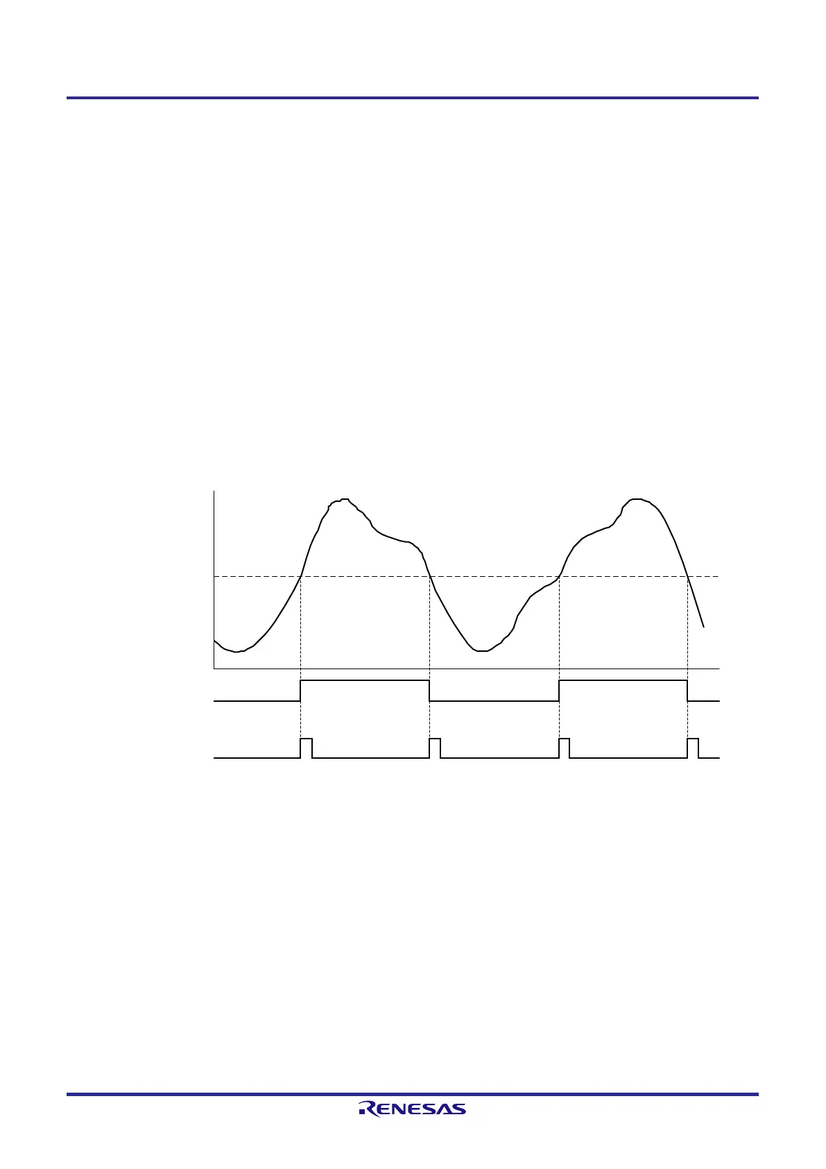
Figure 11-6 shows an example of the comparator n operation (no digital filter (CnFCK1 and CnFCK0 in COMPFIR =
00B), both-edge detection on an interrupt (CnEDG = 1).
Remark n = 0, 1
Figure 11-6. Example of Comparator n (n = 0, 1) Operation (No Digital Filter, Both-Edge Detection on Interrupt)
1
0
1
0
(A) (B) (A) (B)
Reference voltage
(IVREFn or internal
reference voltage
(0.815 V (typ.)))
CnMON bit in
COMPMDR register
Note 1
Comparator detection n
interrupt (INTCMPn)
Analog input voltage (V)
Note 1. The output delay time depends on the comparator operating mode. For details, see 23.6.2 Comparator
characteristics and 24.6.2 Comparator characteristics.
Caution When the rising edge is specified as an effective edge for an interrupt (CnEDG = 0 and CnEPO = 0),
INTCMPn only changes at (A).
When the falling edge is specified as an effective edge for an interrupt (CnEDG = 0 and CnEPO = 1),
INTCMPn only changes at (B).
 Loading...


