RL78/G15 CHAPTER 6 TIMER ARRAY UNIT
R01UH0959EJ0110 Rev.1.10 Page 255 of 765
Mar 7, 2023
6.8.6 Operation as delay counter
It is possible to start counting down when the valid edge of the TImn pin input is detected (an external event), and then
generate INTTMmn (a timer interrupt) after any specified interval.
It is also possible to start counting down and generate INTTMmn (a timer interrupt) at any interval by setting TSmn to 1
by software while TEmn = 1.
The interrupt generation period can be calculated by the following expression.
Generation period of INTTMmn (timer interrupt) = Period of count clock × (Set value of TDRmn + 1)
Timer count register mn (TCRmn) operates as a down counter in the one-count mode.
When the channel start trigger bit (TSmn, TSHm1, TSHm3) of timer channel start register m (TSm) is set to 1, the TEmn,
TEHm1, TEHm3 bits are set to 1 and the TImn pin input valid edge detection wait status is set.
Timer count register mn (TCRmn) starts operating upon TImn pin input valid edge detection and loads the value of timer
data register mn (TDRmn). The TCRmn register counts down from the value of the TDRmn register it has loaded, in
synchronization with the count clock. When TCRmn = 0000H, it outputs INTTMmn and stops counting until the next TImn
pin input valid edge is detected.
The TDRmn register can be rewritten at any time. The new value of the TDRmn register becomes valid from the next
period.
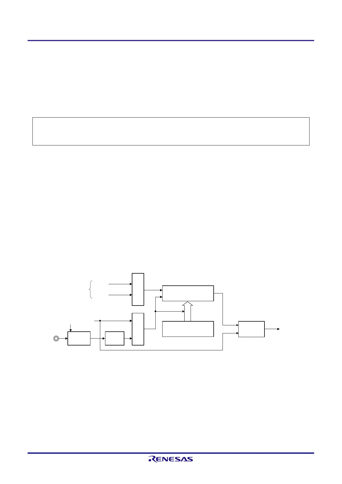
Figure 6-60. Block Diagram of Operation as Delay Counter
Interrupt signal
(INTTMmn)
Timer data register mn
(TDRmn)
TImn pin
Timer counter register mn
(TCRmn)
Interrupt
controller
Edge
detection
Noise filter
TNFENmn
CKm
0
CKm1
Operation clock
Note 1
TSmn
Clock selection
Trigger
selection
Note 1. For channels 1 and 3, the clock can be selected from CKm0, CKm1, CKm2 and CKm3.
Remark m: Unit number (m = 0), n: Channel number (n = 0 to 7)
 Loading...


