RL78/G15 APPENDIX A REVISION HISTORY
R01UH0959EJ0110 Rev.1.10 Page 758 of 765
Mar 7, 2023
APPENDIX A REVISION HISTORY
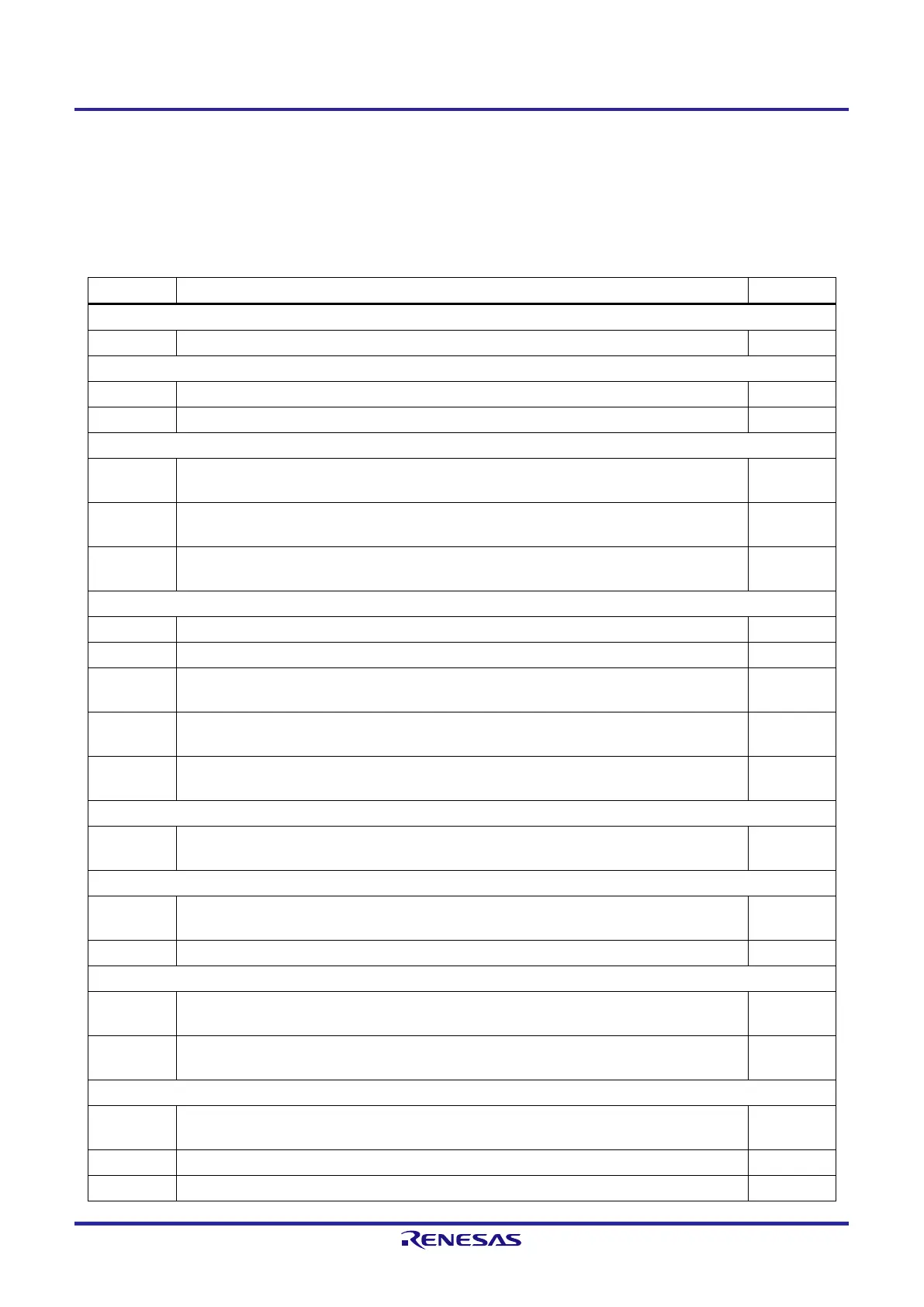
A.1 Major Revisions in This Edition
Page Description Classification
CHAPTER 1 OUTLINE
p.38 to p.41 2.1.1 8-pin products to 2.1.4 20-pin products: The order of pin names in Alternate Function, modified (c)
CHAPTER 3 CPU ARCHITECTURE
p.55 3.1 Overview: The section, added (c)
p.60 Table 3-3. Vector Table: The description of 16-, 10-, and 8-pins, modified (a)
CHAPTER 4 PORT FUNCTIONS
p.107, p.108
Figure 4-3. Format of Pull-up Resistor Option Registers 0, 2, 4, 12 (PU0, PU2, PU4, PU12): The
figure title, modified. Note 1, modified.
(a) (c)
p.117
Table 4-6. Concept of Basic Settings: Output Settings of Unused Alternate Function (Output Function
for SAU), modified
(a)
p.118 to
p.125
Table 4-7. Setting Examples of Registers and Output Latches When Using Pin Function: Alternate
Function Output (SAU Output Function), modified
(a)
CHAPTER 13 SERIAL INTERFACE IICA
p.535 13.5.4 Acknowledge (ACK): The description on the setting of the clock stretch timing, modified (c)
p.537, p.538 Figure 13-19. Clock Stretching: The titles for (1) and (2), modified (c)
p.541
13.5.8 Interrupt request (INTIICA0) generation timing and clock stretching control: The description of
(4), modified
(c)
p.586, p.588,
p.590, p.592
Figure 13-31. Example of Master to Slave Communications: WTIM0, modified (c)
p.594, p.596,
p.598
Figure 13-32. Example of Slave to Master Communications: WTIM0, modified (c)
CHAPTER 14 INTERRUPT FUNCTIONS
p.606
Table 14-2. Flags Corresponding to Interrupt Request Sources (2/2): The description of 10- and 8-
pins of INTIICA0, modified
(a)
CHAPTER 19 FLASH MEMORY
p.660
19.2 Writing to Flash Memory by Using External Device (that Incorporates UART): The description,
modified
(c)
p.661 Figure 19-4. Communication with External Device: The signal name of the external device, modified (a)
CHAPTER 20 ON-CHIP DEBUG FUNCTION
p.685
20.2 Connecting External Device (that Incorporates UART): The signal name of the external device in
the figure, modified
(a)
p.687
Figure 20-3. Memory Spaces Where Debug Monitor Programs Are Allocated: The address value of
internal RASM, deleted. Note 3, modified.
(c)
CHAPTER 23 ELECTRICAL SPECIFICATIONS (T
A
= −40 to +85°C)
p.709
CHAPTER 23 ELECTRICAL SPECIFICATIONS (T
A
= −40 to +85°C): The section title, modified.
Caution 3, deleted.
(c)
p.711 23.2.2 On-chip oscillator characteristics: Note 3, deleted (c)
p.714 23.3.2 Supply current characteristics: Note 1, modified (c)
 Loading...


