RL78/G15 CHAPTER 4 PORT FUNCTIONS
R01UH0959EJ0110 Rev.1.10 Page 107 of 765
Mar 7, 2023
4.3.3 Pull-up resistor option registers 0, 2, 4, 12 (PU0, PU2, PU4, PU12)
These registers specify whether the on-chip pull-up resistors are to be used or not. On-chip pull-up resistors can be used
in 1-bit units only for the bits that satisfy the following usage conditions for the pins to which the use of an on-chip pull-up
resistor has been specified in these registers.
Usage conditions of the on-chip pull-up resistor:
●
PMmn = 1 (Input mode)
●
PMCmn = 0 (Digital I/O)
●
POMmn = 0 (Normal output mode)
On-chip pull-up resistors cannot be connected to bits set to output mode and bits used as alternate-function output pins
and analog setting (PMC = 1), regardless of the settings of these registers.
These registers can be set by a 1-bit or 8-bit memory manipulation instruction.
Reset signal generation sets PU4 to 01H, PU12 to 20H, and clears PU0 and PU2 to 00H.
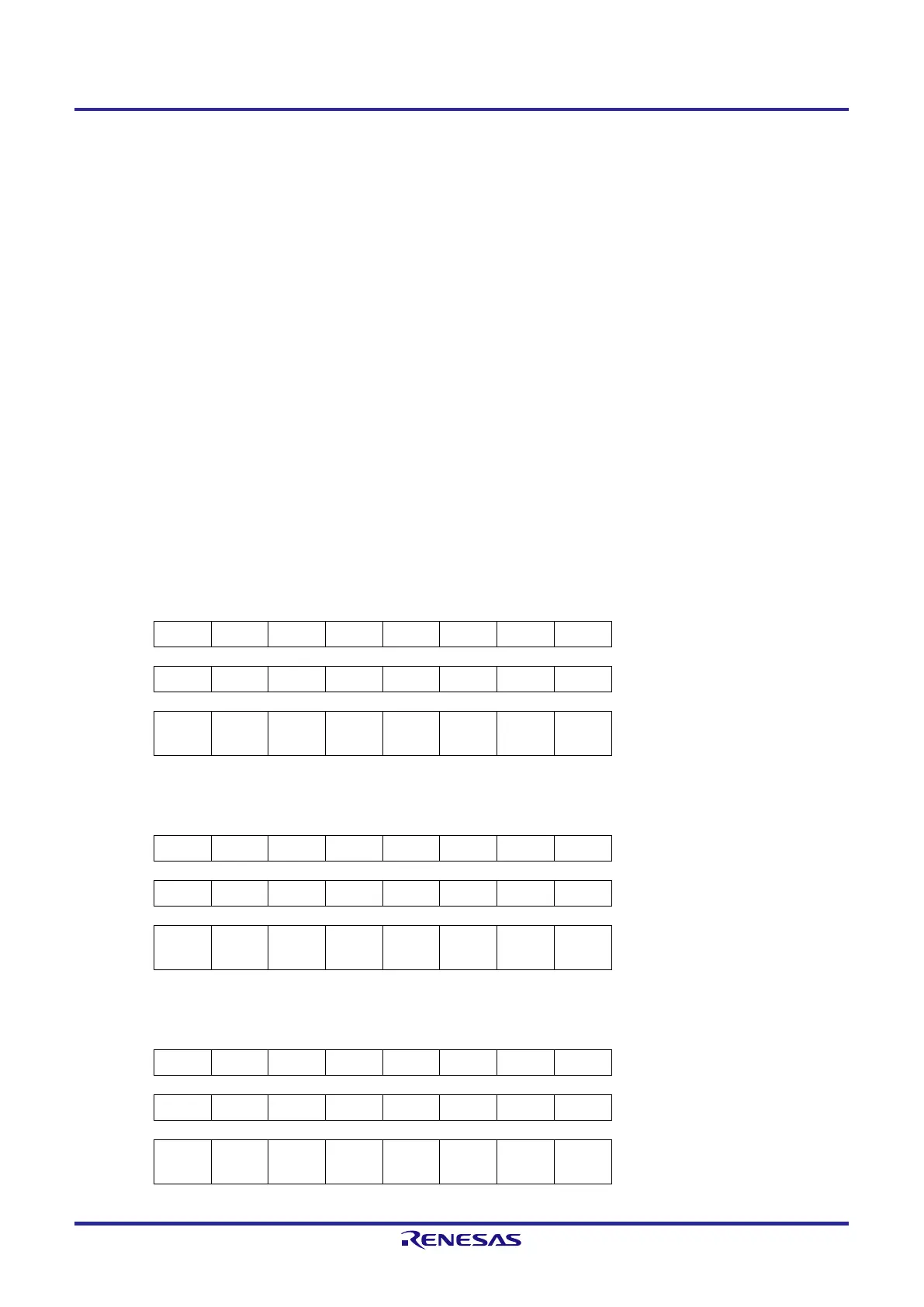
Figure 4-3. Format of Pull-up Resistor Option Registers 0, 2, 4, 12 (PU0, PU2, PU4, PU12)
8-pin products
Symbol 7 6 5 4 3 2 1 0 Address After reset R/W
PU0 0 0 0 PU04 PU03 0 PU01 0 F0030H 00H R/W
PU4 0 0 0 0 0 0 0 PU40 F0034H 01H R/W
PU12 0 0
PU125
Note 1
0 0 0 0 0 F003CH 20H R/W
10-pin products
Symbol 7 6 5 4 3 2 1 0 Address After reset R/W
PU0 0 0 0 PU04 PU03 PU02 PU01 PU00 F0030H 00H R/W
PU4 0 0 0 0 0 0 0 PU40 F0034H 01H R/W
PU12 0 0
PU125
Note 1
0 0 0 0 0 F003CH 20H R/W
16-pin products
Symbol 7 6 5 4 3 2 1 0 Address After reset R/W
PU0 PU07 PU06 PU05 PU04 PU03 PU02 PU01 PU00 F0030H 00H R/W
PU4 0 0 0 0 0 0 PU41 PU40 F0034H 01H R/W
PU12 0 0
PU125
Note 1
0 0 PU122 PU121 0 F003CH 20H R/W
 Loading...


