RL78/G15 CHAPTER 12 SERIAL ARRAY UNIT
R01UH0959EJ0110 Rev.1.10 Page 470 of 765
Mar 7, 2023
12.6.2 UART Reception
UART reception is an operation wherein the RL78 microcontroller asynchronously receives data from another device
(start-stop synchronization).
For UART reception, the odd-number channel of the two channels used for UART is used. The SMR register of both the
odd- and even-numbered channels must be set.
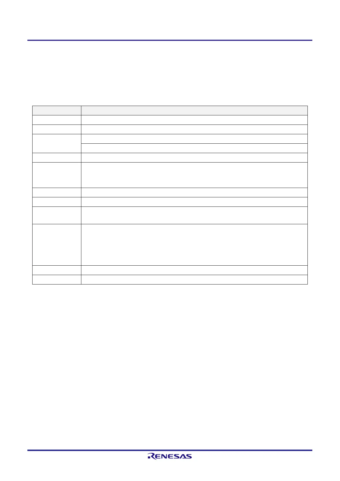
UART UART0
Target channel Channel 1 of SAU0
Pins used RxD0
Interrupt INTSR0
Transfer end interrupt only (Setting the buffer empty interrupt is prohibited.)
Error interrupt INTSRE0
Error detection flag
●
Framing error detection flag (FEFmn)
●
Parity error detection flag (PEFmn)
●
Overrun error detection flag (OVFmn)
Transfer data length 7, 8, or 9 bits
Transfer rate
Note 1
Max. f
MCK
/6 [bps] (SDRmn[15:9] = 2 or more), Min. f
CLK
/(2 × 2
15
× 128) [bps]
Data phase Non-reverse output (default: high level)
Reverse output (default: low level)
Parity bit The following selectable
●
No parity bit (no parity check)
●
No parity judgment (0 parity)
●
Even parity check
●
Odd parity check
Stop bit Appending 1 bit
Data direction MSB or LSB first
Note 1. Use this operation within a range that satisfies the conditions above and the peripheral functions
characteristics specified in the electrical characteristics. For details, see CHAPTER 23 ELECTRICAL
SPECIFICATIONS (T
A
= −40 to +85°C) and CHAPTER 24 ELECTRICAL SPECIFICATIONS (T
A
= −40 to
+105°C, T
A
= −40 to +125°C).
Remark 1. f
MCK
: Operation clock frequency of target channel
f
CLK
: System clock frequency
Remark 2. m: Unit number (m = 0), n: Channel number (n = 1), mn = 01
 Loading...


