RL78/G15 CHAPTER 5 CLOCK GENERATOR
R01UH0959EJ0110 Rev.1.10 Page 134 of 765
Mar 7, 2023
5.3.1 Clock operation mode control register (CMC)
This register is used to set the operation mode of the X1/P121/TI07/TO07/(INTP3) and
X2/EXCLK/P122/TI05/TO05/(INTP2) pins, and to select a gain of the oscillator.
The CMC register can be written only once by an 8-bit memory manipulation instruction after reset release. This register
can be read by an 8-bit memory manipulation instruction.
Reset signal generation clears this register to 00H.
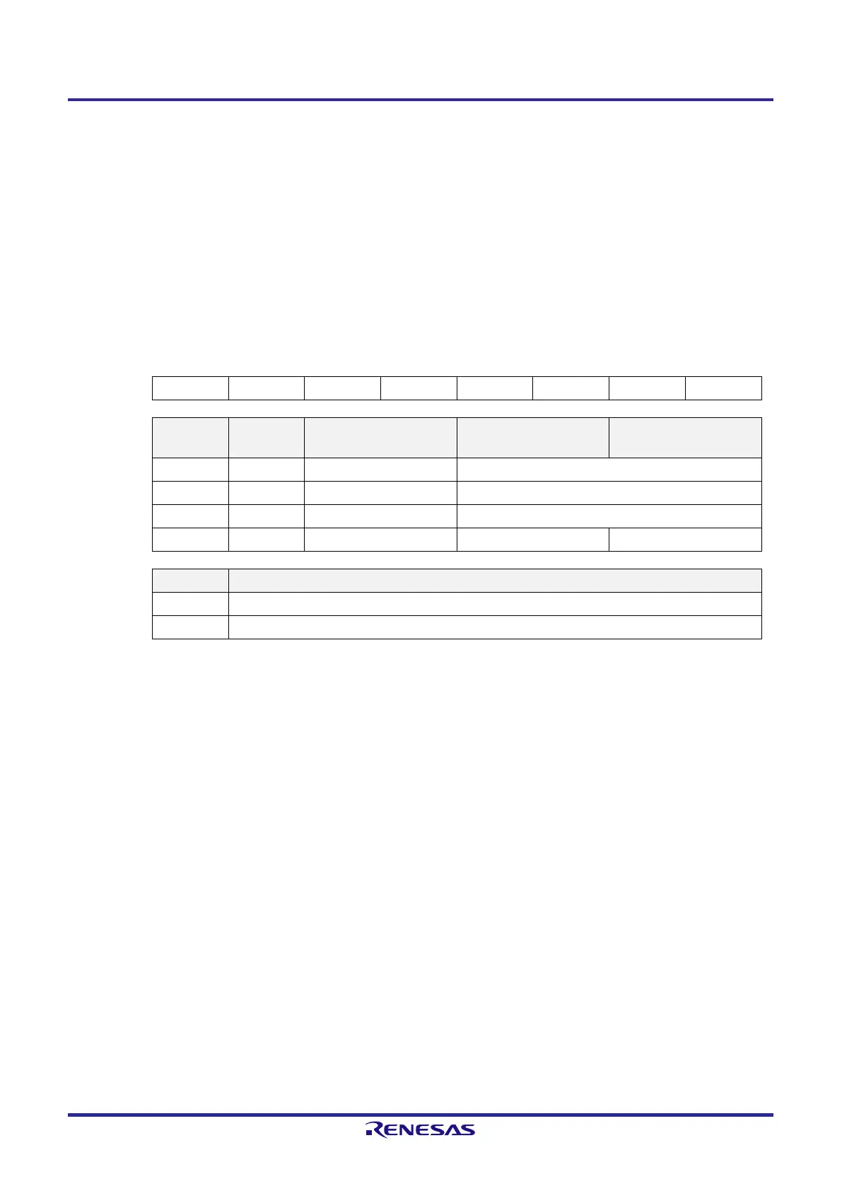
Figure 5-2. Format of Clock Operation Mode Control Register (CMC)
Address: FFFA0H After reset: 00H R/W
Symbol 7 6 5 4 3 2 1 0
CMC EXCLK OSCSEL 0 0 0 0 0 AMPH
EXCLK OSCSEL
High-speed system clock
pin operation mode
X1/P121/TI07/TO07/
(INTP3) pin
X2/EXCLK/P122/TI05/
TO05/(INTP2) pin
0 0 I/O port mode I/O port
0 1 X1 oscillation mode Crystal/ceramic resonator connection
1 0 I/O port mode I/O port
1 1 External clock input mode I/O port External clock input
AMPH Control of X1 clock oscillation frequency
0 1 MHz ≤ f
X
≤ 10 MHz
1 10 MHz ≤ f
X
≤ 12 MHz
Caution 1. The CMC register can be written only once after reset release, by an 8-bit memory manipulation
instruction. When using the CMC register with its initial value (00H), be sure to set the register to
00H after a reset ends in order to prevent malfunction due to a program loop. Such a malfunction
becomes unrecoverable when a value other than 00H is mistakenly written.
Caution 2. After reset release, set the CMC register before X1 oscillation is started as set by the clock
operation status control register (CSC).
Caution 3. Be sure to set the AMPH bit to 1 if the X1 clock oscillation frequency exceeds 10 MHz. Specify the
settings for the AMPH bits while f
IH
is selected as f
CLK
after a reset ends (before f
CLK
is switched to
f
MX
).
Caution 4. Switch the operation mode of the X1 pin and X2 pin only when MSTOP = 1.
Remark f
X
: X1 clock frequency
 Loading...


