RL78/G15 CHAPTER 12 SERIAL ARRAY UNIT
R01UH0959EJ0110 Rev.1.10 Page 386 of 765
Mar 7, 2023
12.3.10 Serial channel enable status register m (SEm)
The SEm register indicates whether data transmission/reception operation of each channel is enabled or stopped.
When 1 is written to a bit of serial channel start register m (SSm), the corresponding bit of this register is set to 1. When
1 is written to a bit of serial channel stop register m (STm), the corresponding bit is cleared to 0.
For channel n whose operation is enabled, the value of the CKOmn bit of serial output register m (SOm) to be described
later cannot be rewritten by software, and a value reflected by a communication operation is output from the serial clock
pin.
For channel n whose operation is stopped, the value of the CKOmn bit of the SOm register can be set by software and is
output from the serial clock pin. In this way, any waveform, such as that of a start condition/stop condition, can be
created by software.
The SEm register can be read by a 16-bit memory manipulation instruction.
The lower 8 bits of the SEm register can be read with a 1-bit or 8-bit memory manipulation instruction with SEmL.
The value of each SEm register is 0000H following a reset.
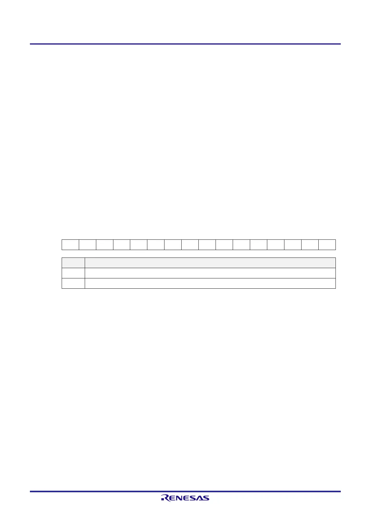
Figure 12-12. Format of Serial Channel Enable Status Register m (SEm)
Address: F0120H, F0121H (SE0) After reset: 0000H R
Symbol 15 14 13 12 11 10 9 8 7 6 5 4 3 2 1 0
SE0 0 0 0 0 0 0 0 0 0 0 0 0 0 0 SE01 SE00
SEmn Indication of whether operation of channel n is enabled or stopped
0 Operation stops.
1 Operation is enabled.
Remark m: Unit number (m = 0), n: Channel number (n = 0, 1)
 Loading...


