RL78/G15 CHAPTER 19 FLASH MEMORY
R01UH0959EJ0110 Rev.1.10 Page 676 of 765
Mar 7, 2023
19.6.1.6 Flash memory sequencer control register (FSSQ)
The FSSQ register defines the commands to be used when the flash memory sequencer is activated.
The FSSQ register can be set by an 8-bit memory manipulation instruction.
This register is set to 00H following a reset.
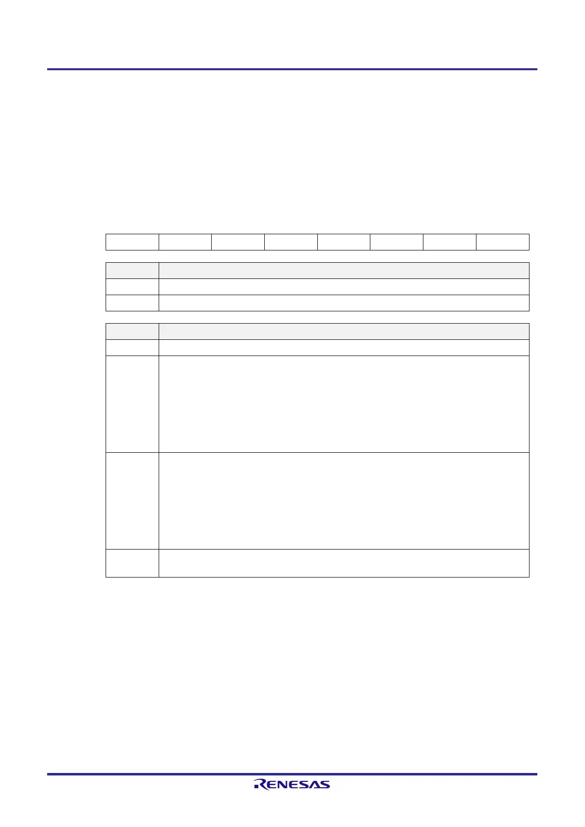
Figure 19-13. Format of Flash Memory Sequencer Control Register (FSSQ)
Address: F00C1H After reset: 00H R/W
Symbol 7 6 5 4 3 2 1 0
FSSQ SQST 0 0 0 0 SQMD2 SQMD1 SQMD0
SQST Flash memory sequencer operation control
0 Stops operation.
1 Starts operation.
SQMD2-0 Flash memory sequencer command selection
000b Initial value (commands not selected)
001b Write
Writes data specified in the FLWHH, FLWHL, FLWLH, and FLWLL registers to the address specified in
the FLAPH and FLAPL registers.
Unit for writing (code flash area):
1 word (4 bytes) (when the SELDFL bit is set to 0)
Unit for writing (data flash area):
1 word (4 bytes) (when the SELDFL bit is set to 1)
100b Block erasure
Erases blocks in the range from the block start address specified in the FLAPH and FLAPL registers to
the block end address specified in the FLSEDH and FLSEDL registers.
Unit for block erasing (code flash area):
1 block (1 Kbyte) (when the SELDFL bit is set to 0)
Unit for block eraing (data flash area):
1 block (512 bytes) (when the SELDFL bit is set to 1)
Other than
above
Setting prohibited
 Loading...


