RL78/G15 CHAPTER 10 A/D CONVERTER
R01UH0959EJ0110 Rev.1.10 Page 327 of 765
Mar 7, 2023
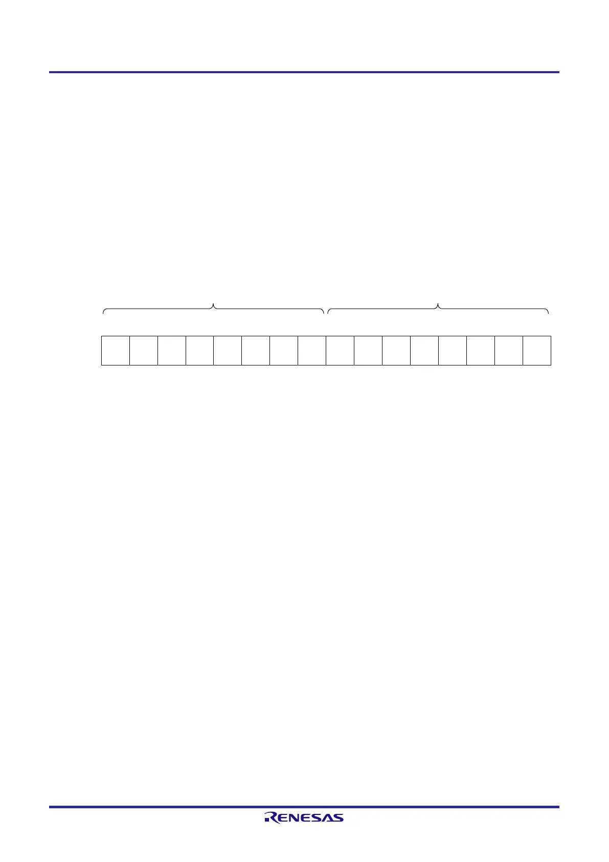
10.3.4 10-bit A/D conversion result register (ADCR)
This is a 16-bit register which holds the result of A/D conversion. The six lower-order bits are fixed to 0. Each time A/D
conversion ends, the conversion result is loaded from the successive approximation register (SAR). The eight higher-
order bits of the conversion result are stored in FFF1FH and the two lower-order bits are stored in the two higher-order
bits of FFF1EH.
The ADCR register can be read by a 16-bit memory manipulation instruction.
Reset signal generation clears this register to 0000H.
Figure 10-7. Storing of the A/D Conversion Result in the Case of 10-bit Resolution
Address: FFF1FH, FFF1EH After reset: 0000H R
FFF1FH FFF1EH
Symbol 15 14 13 12 11 10 9 8 7 6 5 4 3 2 1 0
ADCR
ADCR
9
ADCR
8
ADCR
7
ADCR
6
ADCR
5
ADCR
4
ADCR
3
ADCR
2
ADCR
1
ADCR
0
0 0 0 0 0 0
Caution 1. When writing to A/D converter mode register 0 (ADM0) and the analog input channel specification
register (ADS), the contents of the ADCR/ADCRH register may become undefined. After conversion
ends, read the conversion result before writing to the ADM0 and ADS registers. Using timing other
than the above may cause an incorrect conversion result to be read.
Caution 2. When the ADCR register is read while 8-bit resolution A/D conversion is selected (when the ADTYP
bit of A/D converter mode register 2 (ADM2) is 1), 0 is read from the two lower-order bits (ADCR1,
ADCR0). Note that, when the ADCR register is read before completion of A/D conversion while 8-bit
resolution A/D conversion is selected, 0 may not be read from the two lower-order bits (ADCR1,
ADCR0).
 Loading...


