RL78/G15 CHAPTER 18 OPTION BYTE
R01UH0959EJ0110 Rev.1.10 Page 649 of 765
Mar 7, 2023
18.2 Format of User Option Byte
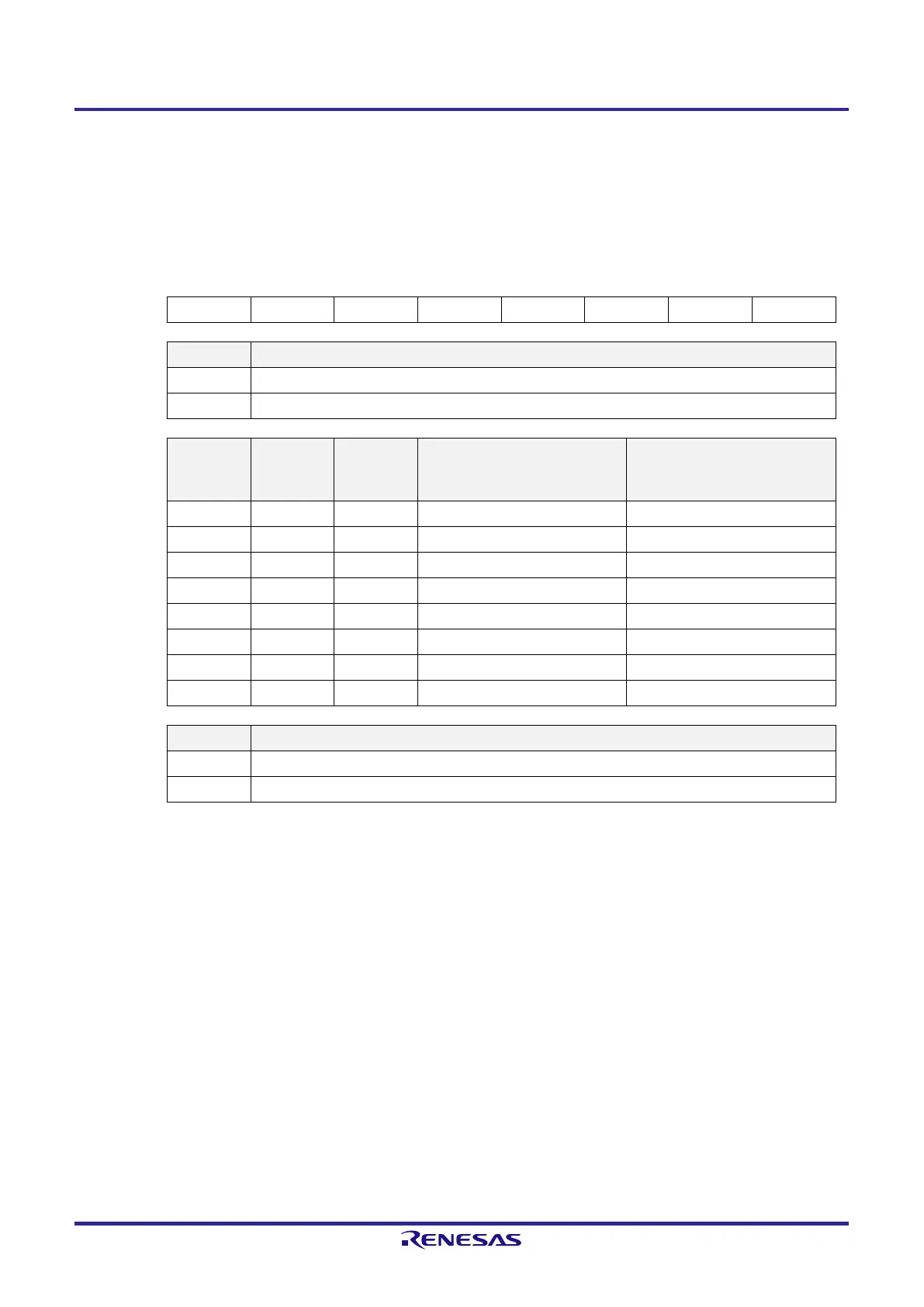
Figure 18-1. Format of User Option Byte (000C0H)
Address: 000C0H
7 6 5 4 3 2 1 0
1 1 1 WDTON WDCS2 WDCS1 WDCS0 WDSTBYON
WDTON Operation control of watchdog timer counter
0 Counter operation disabled (counting stopped after reset)
1 Counter operation enabled (counting started after reset)
WDCS2 WDCS1 WDCS0
Watchdog timer
overflow time
(f
IL
= 17.25 kHz (MAX.))
Watchdog timer
interval interrupt time
(f
IL
= 17.25 kHz (MAX.))
0 0 0 (2
6
−1)/f
IL
(3.65 ms) 2
6
/f
IL
× 0.75 (2.78 ms)
0 0 1 (2
7
−1)/f
IL
(7.36 ms) 2
7
/f
IL
× 0.75 (5.56 ms)
0 1 0 (2
8
−1)/f
IL
(14.7 ms) 2
8
/f
IL
× 0.75 (11.1 ms)
0 1 1 (2
9
−1)/f
IL
(29.6 ms) 2
9
/f
IL
× 0.75 (22.2 ms)
1 0 0 (2
11
−1)/f
IL
(118 ms) 2
11
/f
IL
× 0.75 (89.0 ms)
1 0 1 (2
13
−1)/f
IL
(474 ms) 2
13
/f
IL
×0.75 (356 ms)
1 1 0 (2
14
−1)/f
IL
(949 ms) 2
14
/f
IL
× 0.75 (712 ms)
1 1 1 (2
16
−1)/f
IL
(3799 ms) 2
16
/f
IL
× 0.75 (2849 ms)
WDSTBYON Operation control of watchdog timer counter (HALT/STOP mode)
0 Counter operation stopped in HALT/STOP mode
1 Counter operation enabled in HALT/STOP mode
Caution 1. Be sure to write 1 to bits 7 to 5.
Caution 2. Setting WDTON = 0 and WDSTBYON = 1 is prohibited.
Caution 3. The watchdog timer always generates an interval interrupt when the specified time is reached
unless this is specifically disabled. If the interval interrupt from the watchdog timer is not to be
used, be sure to disable the interrupt by setting the WDTIMK bit to 1.
Remark f
IL
: Low-speed on-chip oscillator clock frequency
 Loading...


