RL78/G15 CHAPTER 6 TIMER ARRAY UNIT
R01UH0959EJ0110 Rev.1.10 Page 190 of 765
Mar 7, 2023
6.3.5 Timer channel enable status register m (TEm)
The TEm register is used to display whether the timer operation of each channel is enabled or stopped.
Each bit of the TEm register corresponds to each bit of the timer channel start register m (TSm) and the timer channel
stop register m (TTm). When a bit of the TSm register is set to 1, the corresponding bit of this register is set to 1. When a
bit of the TTm register is set to 1, the corresponding bit of this register is cleared to 0.
The TEm register can be read by a 16-bit memory manipulation instruction.
The lower 8 bits of the TEm register can be set with a 1-bit or 8-bit memory manipulation instruction with TEmL.
Reset signal generation clears this register to 0000H.
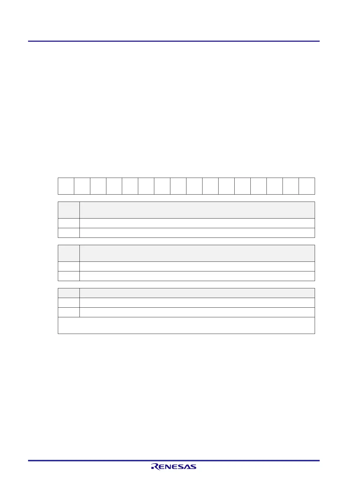
Figure 6-13. Format of Timer Channel Enable Status register m (TEm)
Address: F01B0H, F01B1H (TE0) After reset: 0000H R
Symbol 15 14 13 12 11 10 9 8 7 6 5 4 3 2 1 0
TEm 0 0 0 0
TEHm
3
0
TEHm
1
0 TEm7 TEm6 TEm5
TEm4 TEm3
TEm2 TEm1
TEm0
TEHm3
Indication of whether operation of the higher 8-bit timer is enabled or stopped when channel 3 is in the 8-bit
timer mode
0 Operation is stopped.
1 Operation is enabled.
TEHm1
Indication of whether operation of the higher 8-bit timer is enabled or stopped when channel 1 is in the 8-bit
timer mode
0 Operation is stopped.
1 Operation is enabled.
TEmn Indication of operation enable/stop status of channel n
0 Operation is stopped.
1 Operation is enabled.
This bit displays whether operation of the lower 8-bit timer for TEm1 and TEm3 is enabled or stopped when channel 1 or 3
is in the 8-bit timer mode.
Remark m: Unit number (m = 0), n: Channel number (n = 0 to 7)
 Loading...


