RL78/G15 CHAPTER 19 FLASH MEMORY
R01UH0959EJ0110 Rev.1.10 Page 671 of 765
Mar 7, 2023
19.6.1.2 Flash end address specification registers H and L (FLSEDH, FLSEDL)
The FLSEDH and FLSEDL registers specify the address where programming of the flash memory is to end.
The FLSEDH and FLSEDL registers can be set by an 8-bit memory manipulation instruction.
These registers are set to 00H following a reset.
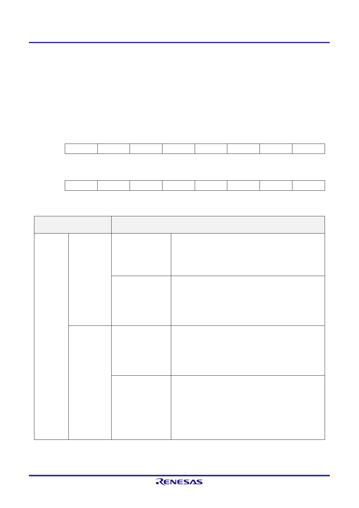
Figure 19-9. Format of Flash End Address Specification Registers H and L (FLSEDH, FLSEDL)
Address: F00C5H After reset: 00H R/W
Symbol 7 6 5 4 3 2 1 0
FLSEDH 0 0 0 EWA12 EWA11 EWA10 EWA9 EWA8
Address: F00C4H After reset: 00H R/W
Symbol 7 6 5 4 3 2 1 0
FLSEDL EWA7 EWA6 EWA5 EWA4 EWA3 EWA2 0 0
Table 19-9. Method of Setting the FLAPH/L and FLSEDH/L Registers
Commands exclusively for use
with the flash memory sequencer
Settings of the FLAPH/L and FLSEDH/L Registers
FSSQ Write Code flash FLAPH/L registers:
Bits 12 to 0 = bits 12 to 0 of the address from which writing is to
proceed
FLSEDH/L registers:
Bits 12 to 0 = All 0s (can be unset)
Data flash FLAPH/L registers:
Bits 12 to 10 = All 0s
Bits 9 to 0 = Bits 9 to 0 of the address from which writing is to
proceed
FLSEDH/L registers:
Bits 12 to 0 = All 0s (can be unset)
Block erase Code flash FLAPH/L registers:
Bits 12 to 10 = bits 12 to 10 of the block start address
Bits 9 to 0 = All 0s
FLSEDH/L registers:
Bits 12 to 10 = bits 12 to 10 of the block start address
Bits 9 to 2 = All 1s
Data flash FLAPH/L registers:
Bits 12 to 10 = All 0s
Bit 9 = bit 9 of the block start address
Bits 8 to 0 = All 0s
FLSEDH/L registers:
Bits 12 to 10 = All 0s
Bit 9 = bit 9 of the block start address
Bits 8 to 2 = All 1s
Caution Set the FLAPH/L registers and the FLSEDH/L registers so that the following condition is met.
FLAPH/L setting ≤ FLSEDH/L setting
 Loading...


