RL78/G15 CHAPTER 13 SERIAL INTERFACE IICA
R01UH0959EJ0110 Rev.1.10 Page 519 of 765
Mar 7, 2023
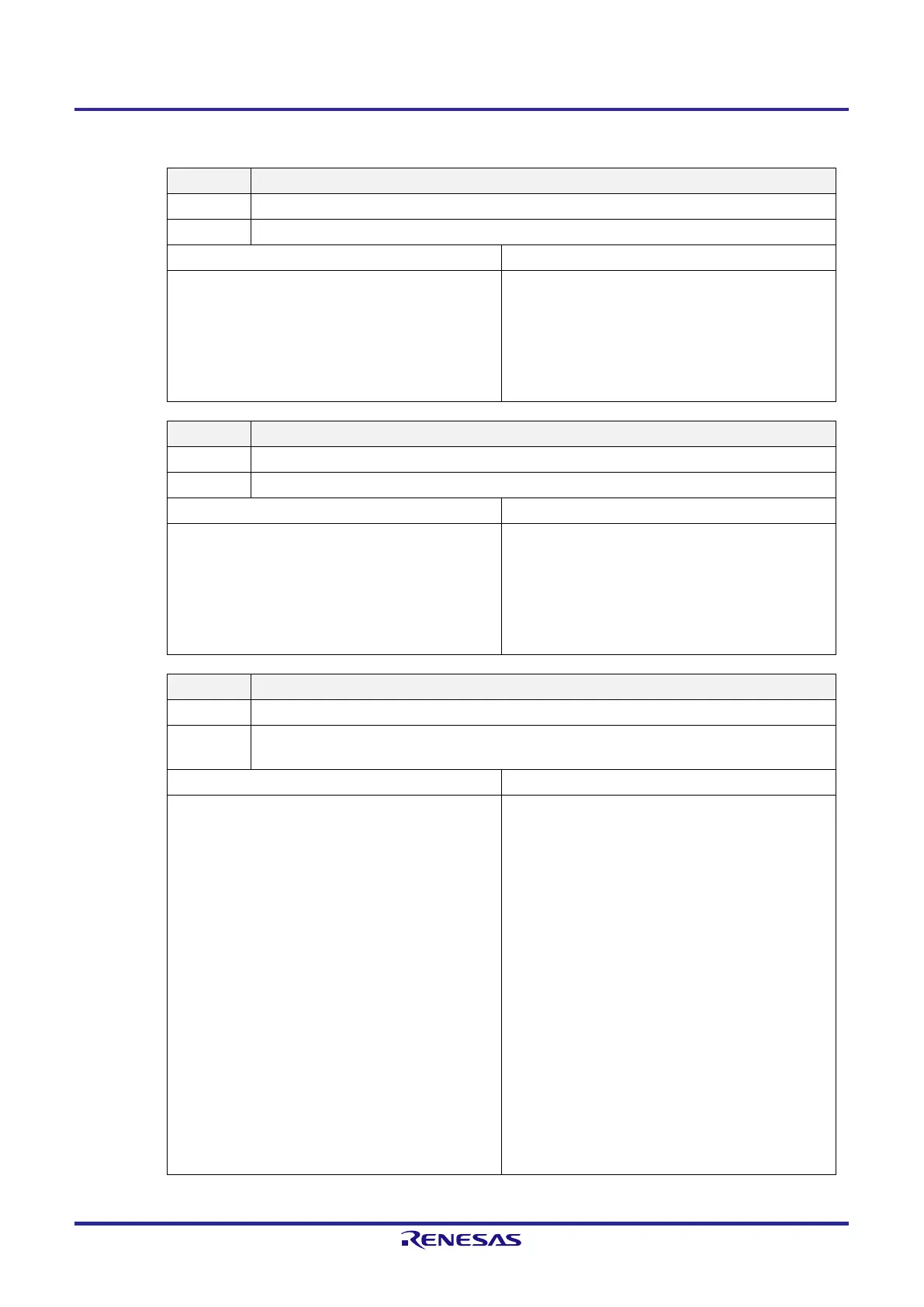
Figure 13-7. Format of IICA Status Register 0 (IICS0) (2/3)
EXC0 Detection of extension code reception
0 Extension code was not received.
1 Extension code was received.
Condition for clearing (EXC0 = 0) Condition for setting (EXC0 = 1)
●
When a start condition is detected
●
When a stop condition is detected
●
Cleared by LREL0 = 1 (exit from communications)
●
When the IICE0 bit changes from 1 to 0 (operation
stop)
●
Reset
●
When the higher four bits of the received address data
is either “0000” or “1111” (set at the rising edge of the
8th clock).
COI0 Address match detection
0 The addresses do not match.
1 The addresses match.
Condition for clearing (COI0 = 0) Condition for setting (COI0 = 1)
●
When a start condition is detected
●
When a stop condition is detected
●
Cleared by LREL0 = 1 (exit from communications)
●
When the IICE0 bit changes from 1 to 0 (operation
stop)
●
Reset
●
When the received address matches the local address
(slave address register 0 (SVA0)) (set at the rising edge
of the 8th clock).
TRC0 Transmission/reception state detection
0 Reception state (not in the transmission state). The SDAA0 line is set to high impedance.
1
Transmission state. Enable the output of the value in the SO0 latch to the SDAA0 line (valid after the
falling edge of the 9th clock of the first byte).
Condition for clearing (TRC0 = 0) Condition for setting (TRC0 = 1)
<Both master and slave>
●
When a stop condition is detected
●
Cleared by LREL0 = 1 (exit from communications)
●
When the IICE0 bit changes from 1 to 0 (operation
stop)
●
Cleared by WREL0 = 1 (clock stretching released)
Note 2
●
When the ALD0 bit changes from 0 to 1 (arbitration
loss)
●
Reset
●
When not participating in communications (MSTS0,
EXC0, COI0 = 0)
<Master>
●
When 1 is output to the LSB (transfer direction
specification bit) of the first byte
<Slave>
●
When a start condition is detected
●
When 0 is input to the LSB (transfer direction
specification bit) of the first byte
<Master>
●
When a start condition is generated
●
When 0 (master transmission) is output to the LSB
(transfer direction specification bit) of the first byte
(during address transfer)
<Slave>
●
When 1 (slave transmission) is input to the LSB
(transfer direction specification bit) of the first byte from
the master (during address transfer)
 Loading...


