RL78/G15 CHAPTER 13 SERIAL INTERFACE IICA
R01UH0959EJ0110 Rev.1.10 Page 517 of 765
Mar 7, 2023
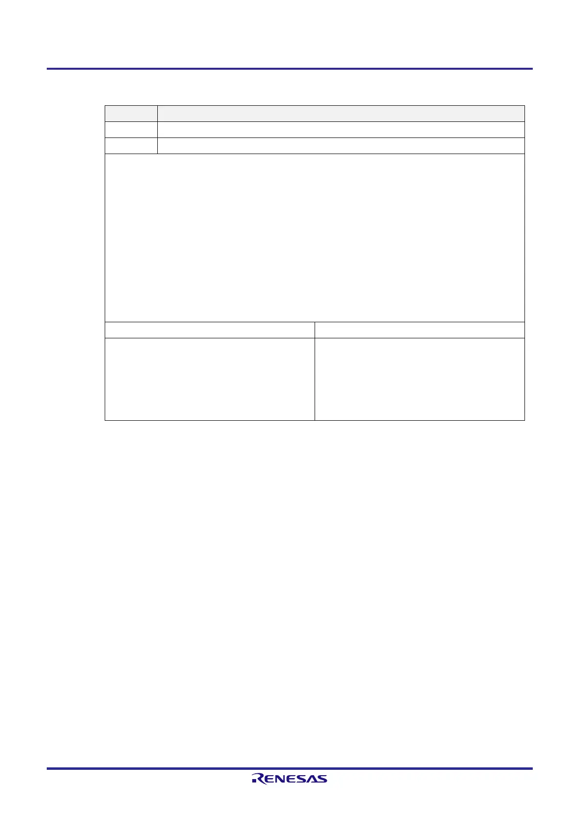
Figure 13-6. Format of IICA Control Register 00 (IICCTL00) (4/4)
SPT0
Note 7
Stop condition trigger
0 A stop condition is not generated.
1 A stop condition is generated (termination of transfer as a master).
Cautions concerning set timing
●
For master reception: Setting this bit to 1 during transfer is prohibited.
It can be set to 1 only during the clock stretch period after the ACKE0 bit has been cleared to 0 and the slave has
been notified of final reception.
●
For master transmission: A stop condition cannot be generated normally during the acknowledge period. Therefore,
set it to 1 during the clock stretch period following the output of the 9th clock.
●
Setting this bit to 1 at the same time as the start condition trigger (STT0) is prohibited.
●
Set the SPT0 bit to 1 only when in master mode.
●
Note that if the SPT0 bit is set to 1 during the clock stretch period following the output of 8 clock pulses while WTIM0
= 0, a stop condition is generated during the high-level period of the 9th clock after clock stretching has been
released. The WTIM0 bit should be changed from 0 to 1 during the clock stretch period following the output of 8
clock pulses, and the SPT0 bit should be set to 1 during the clock stretch period following the 9th clock output.
●
Once the SPT0 bit is set to 1, setting it to 1 again before the clear condition is met is prohibited.
Condition for clearing (STT0 = 0) Condition for setting (STT0 = 1)
●
A loss in arbitration
●
Automatically cleared after the detection of the stop
condition
●
Cleared by LREL0 = 1 (exit from communications)
●
When IICE0 = 0 (operation stop)
●
Reset
●
Set by instruction
Note 1. The IICA status register 0 (IICA0), the STCF0 and IICBSY0 bits of IICA flag register 0 (IICF0), and the CLD0
and DAD0 bits of IICA control register 01 (IICCTL01) are reset.
Note 2. The signal of this bit is invalid while IICE0 = 0.
Note 3. Reading the LREL0 and WREL0 bits always returns 0.
Note 4. The signal of this bit is invalid while IICE0 = 0. Set this bit during that period.
Note 5. The set value is invalid during address transfer and if the code is not an extension code.
When the device serves as a slave and the addresses match, an acknowledgment is generated regardless of
the set value.
Note 6. The STT0 bit is always read as 0.
Note 7. The SPT0 bit is always read as 0.
Caution 1. If the operation of I
2
C is enabled (IICE0 = 1) when the SCLA0 line is at the high level, the SDAA0 line
is at the low level, and the digital filter is turned on (DFC0 of the IICCTL01 register = 1), a start
condition will be inadvertently detected immediately. In this case, set (1) the LREL0 bit by using a
1-bit memory manipulation instruction immediately after enabling operation of I
2
C (IICE0 = 1).
Caution 2. While bit 3 (TRC0) of IICA status register 0 (IICS0) is 1 (transmission state), if bit 5 (WREL0) of IICA
control register 00 (IICCTL00) is set to 1 at the 9th clock to release clock stretching, the TRC0 bit is
cleared (reception state) and the SDAA0 line is set to the high impedance state. Release clock
stretching while the TRC0 bit is 1 (transmission state) by writing to IICA shift register 0.
Remark IICRSV0: Bit 0 of IICA flag register 0 (IICF0)
STCF0: Bit 7 of IICA flag register 0 (IICF0)
 Loading...


