RL78/G15 CHAPTER 6 TIMER ARRAY UNIT
R01UH0959EJ0110 Rev.1.10 Page 237 of 765
Mar 7, 2023
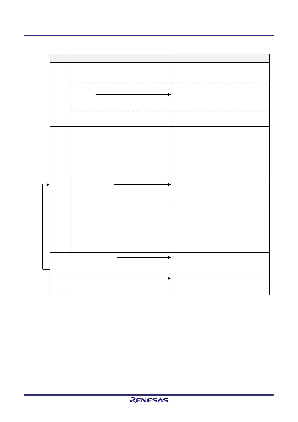
Figure 6-47. Operation Procedure When External Event Counter Function Is Used
Software Operation Hardware Status
TAU
default
setting
Power-off status
(Clock supply is stopped and writing to each register
is disabled.)
Sets the TAUmEN bit of peripheral enable register 0
(PER0) to 1.
Power-on status. Each channel stops operating.
(Clock supply is started and writing to each register is
enabled.)
Sets timer clock select register m (TPSm).
Determines clock frequencies of CKm0 to CKm3.
Channel
default
setting
Sets the corresponding bit of the noise filter enable
register 1 (NFEN1) to 0 (off) or 1 (on).
Sets timer mode register mn (TMRmn) (determines
operation mode of channel).
Sets number of counts to timer data register mn
(TDRmn).
Clears the TOEmn bit of timer output enable register
m (TOEm) to 0.
Channel stops operating.
(Clock is supplied and some power is consumed.)
Operation is resumed.
Operation
start
Sets the TSmn bit to 1.
The TSmn bit automatically returns to 0 because it
is a trigger bit.
TEmn = 1, and count operation starts.
Value of the TDRmn register is loaded to timer
count register mn (TCRmn) and detection of the
TImn pin input edge is awaited.
During
operation
Set value of the TDRmn register can be changed.
The TCRmn register can always be read.
The TSRmn register is not used.
Set values of the TMRmn register, TOMmn, TOLmn,
TOmn, and TOEmn bits cannot be changed.
Counter (TCRmn) counts down each time input edge
of the TImn pin has been detected. When count value
reaches 0000H, the value of the TDRmn register is
loaded to the TCRmn register again, and the count
operation is continued. By detecting TCRmn = 0000H,
the INTTMmn output is generated.
After that, the above operation is repeated.
Operation
stop
The TTmn bit is set to 1.
The TTmn bit automatically returns to 0 because it
is a trigger bit.
TEmn = 0, and count operation stops.
The TCRmn register holds count value and stops.
TAU stop
The TAUmEN bit of the PER0 register is cleared
to 0.
Power-off status
All circuits are initialized and SFR of each channel
is also initialized.
Remark m: Unit number (m = 0), n: Channel number (n = 0 to 7)
 Loading...


