RL78/G15 CHAPTER 13 SERIAL INTERFACE IICA
R01UH0959EJ0110 Rev.1.10 Page 562 of 765
Mar 7, 2023
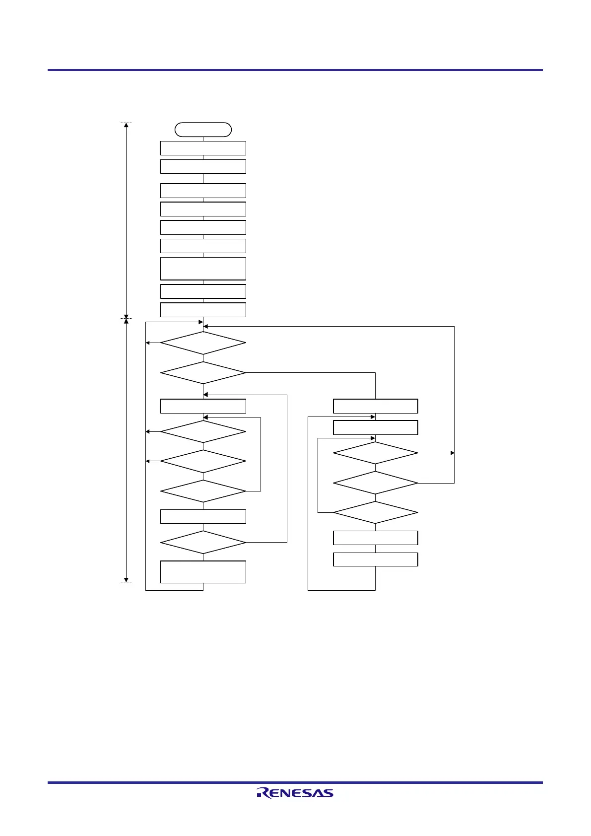
Figure 13-29. Slave Operation Procedure (1)
Release serial interface IICA0 from the reset state and start
clock supply.
START
Set the PER0 register
Set the port
IICWL0, IICWH0 ← xxH
SVA0 ← xxH
IICF0 ← 0xH
Set IICRSV0
Set IICCTL01
IICCTL00 ← 0xx011xxB
ACKE0 = WTIM0 = 1,
SPIE0 = 0
IICCTL00 ← 1xx011xxB
IICE0 = 1
Set the port
Setting of the port multiplexed with the pin to be used
First, set the port to input mode and the output latch to 0
(see 13.3.8 Registers controlling port functions of IICA serial input/output pins).
Set the transfer clock
Set the local address
Set the start condition
Set the port from input mode to output mode and enable the output of the I
2
C bus
(see 13.3.8 Registers controlling port functions of IICA serial input/output pins).
Yes
Communication processing Initial settings
Communication
mode flag = 1?
No
Communication
direction flag = 1?
Write IICA0
Yes
Communication
mode flag = 1?
Communication
direction flag = 1?
Ready flag = 1?
Clear the ready flag
ACKD0 = 1?
Clear the communication
mode flag
WREL0 = 1
Yes
No
No
No
No
Yes
Yes
Yes
Start
transmission
SPIE0 = 1
WREL0 = 1
Communication
mode flag = 1?
Communication
direction flag = 0?
Ready flag = 1?
Read IICA0
Clear the ready flag
No
No
Yes
No
Yes
Yes
No
Start
reception
Remark Conform to the specifications of the product that is communicating, with respect to the transmission and
reception formats.
 Loading...


