Powering expanders from the auxiliary power terminals
Installation & Configuration Manual
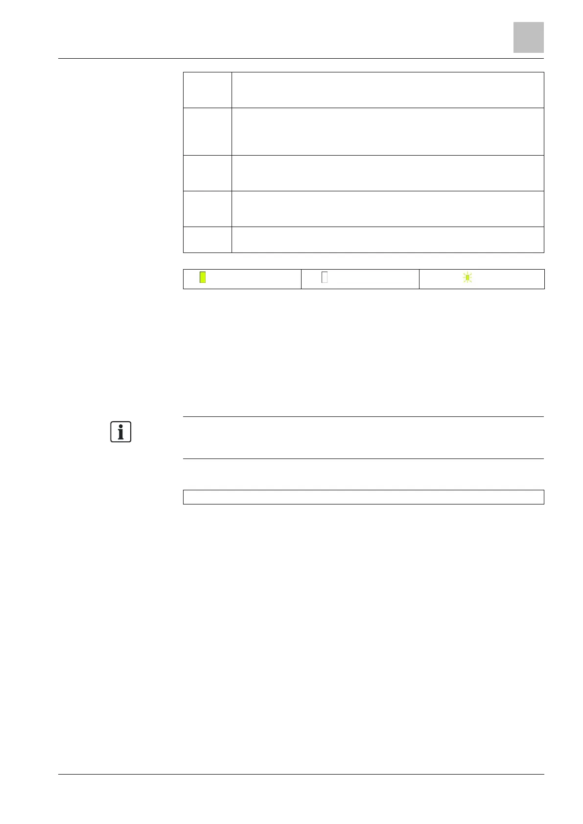
ON: Mains failure
OFF: Mains OK
ON: X-BUS configuration is a loop configuration
OFF: X-BUS configuration is an spur configuration
FLASHING: Detects end of line Expanders or break in wiring.
ON: a hardware fault has been detected on the board
OFF: no hardware fault has been detected
ON: system is writing to flash memory
OFF: system is not writing to flash memory
FLASHING: system is functioning normally
23.3 Powering expanders from the auxiliary power
terminals
To calculate the number of expanders/keypads that can safely be powered from
the auxiliary 12 VDC power terminals, add the total maximum current draw from all
of the expanders/keypads to be powered and determine if this total is less than the
specified 12VDC auxiliary power.
Please refer to Technical data for the specific auxiliary current and to the
corresponding installation instruction or data sheet of modules, keypads and
expanders for current consumption.
Expander 1 Current (mA) + Expander 2 Current (mA) + ….. <Auxiliary Power
If the electronic or relay outputs are already powering external devices, the power
supplied to these devices must be subtracted from the 12VDC auxiliary power
supply to determine the amount of available power from the auxiliary power
terminals (0 V 12 V).
If the total maximum current draw from the expanders exceeds the auxiliary power,
a PSU expander should be used to provide additional power.
 Loading...