Mounting system equipment
Installation & Configuration Manual
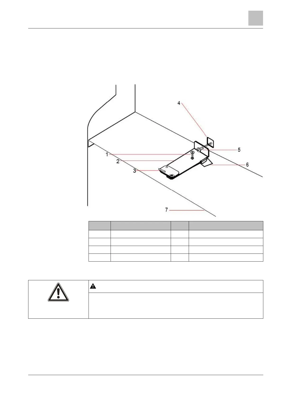
4. Mount the G5 housing in the appropriate position on the wall and tighten the 4
mounting screws. Ensure that the housing is flush with the wall surface.
5. Move the tamper bracket to the far left of the orientation slot and tighten the
back tamper screw (item 5) to the wall. The tamper bracket should be
perpendicular to the back wall of the housing.
6. Install the lid on the housing to test the tamper switch connection. Lift the lid by
approximately 1 mm to activate the tamper switch.
Front tamper securing screw
Shelf separating battery compartment
If the back tamper screw is not secure against the wall, then tamper protection is
compromised. If the housing is removed from the wall or displaced, the back
tamper contact needs to be tested again for proper functionality and re-adjusted if
required.
6.3.2.1 Tamper operation
Tamper switch - normal
 Loading...