Installation & Configuration Manual
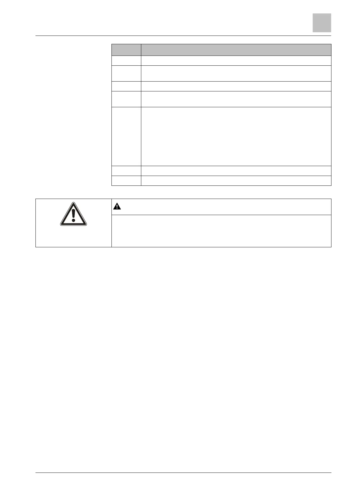
JP1 — Front tamper bypass must be fitted.
Buzzer — Activated to locate the expander. See the X-BUS menu LOCATE
[➙ 120] for more information.
JP6 — Back tamper bypass. Must be fitted.
Manual addressing switches — Enable manual setting of the ID of the
expander.
X-BUS Status LED — Indicates the X-BUS status, when the system is in Full
Engineer mode, as follows:
Slow flash (every 1.5 seconds) — X-BUS communications status is OK.
Quick flash (every 0.2 seconds) — Indicates one of the following:
– Indicates the last-in-line expander for spur configurations.
– Indicates a communications problem between two expanders. If two
adjacent expanders are flashing quickly, the problem exists between
those two expanders.
The combined maximum load current drawn from all 12V DC outputs (OP 1 - 8)
plus COMM1, should not exceed 2.4A. Each individual output, and output A2,
should not exceed 300mA. If the device current requires more than 300mA, it is
recommended to parallel the outputs.
Adding extra expanders
If adding extra expanders to the G5 enclosure, you must ensure the front and back
tampers are deactivated by fitting the appropriate jumpers. In a G5 enclosure, the
front and back tamper is handled by the enclosure itself and the SPCP355.300
Smart PSU.
7.1.1 Supervised Outputs
The SPCP355.300 Smart PSU supports three, open-drain, logical outputs, which
can be supervised for tamper detection. Output tamper detection is enabled by
configuration. Output tamper detection is enabled by connecting a 4K7 EoL resistor
in parallel with the load device, such as an external bell. A power diode (1N4001
for example, or similar) is also required, if not already present in the external
device.
 Loading...