Network cable connections
Installation & Configuration Manual
23 Appendix
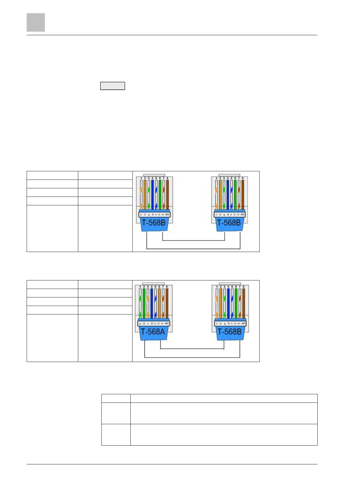
23.1 Network cable connections
A PC can be connected directly to the Ethernet interface of the SPC controller or
via a LAN connection. The tables below show the 2 possible connection
configurations.
If the SPC is connected to an existing network via a hub, then connect a
straight through cable from the hub to the SPC and another from the hub to the
PC.
If the controller is not connected to a network (i.e. a hub or switch is not used),
then a crossover cable should be connected between the SPC controller and
the PC.
Use the straight through cable for connecting the SPC controller to a PC via a hub.
Use the crossover cable for connecting the SPC controller directly to a PC.
23.2 Controller status LEDs
FLASHING: wireless data is being received by the wireless module
OFF: no wireless data is being received
ON: battery voltage has dropped below the deep discharge level (10.9 V)
OFF: battery status OK
 Loading...