Mounting system equipment
Installation & Configuration Manual
6 Mounting system equipment
6.1 Mounting a G2 housing
The SPC G2 housing is supplied with a metallic or plastic cover. The cover is
attached to the base of the housing by 2 securing screws located on the top and
bottom of the front cover.
To open the housing, remove both screws with the appropriate screwdriver and lift
the cover directly from the base.
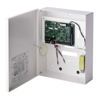
The G2 housing contains the controller PCB (Printed Circuit Board) mounted on 4
support pillars. An optional input/output module can be mounted directly beneath
the controller PCB. A battery with capacity of 7 Ah max. can be accommodated
below the controller.
An optional external antenna must be fitted to housings with metallic lid if the
wireless functionality is required. If an antenna is fitted to the unit, it must be
enabled in the firmware.
The SPC G2 housing provides 3 screw holes for wall mounting the unit.
To wall mount the housing, remove the cover and locate the initial fixing screw hole
at the top of the cabinet. Mark the position of this screw hole on the desired
location on the wall and drill the initial screw hole. Screw the unit to the wall and
mark the position of the bottom 2 screw hole positions with the unit vertically
aligned.
Screws with a 4-5 mm shank, a minimum head diameter of 8 mm and a minimum
length of 40 mm are recommended for mounting the housing. Additional expansion
plugs or fixings may be required depending on the construction of the wall.
 Loading...