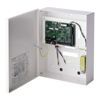
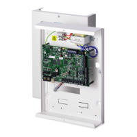
Controller Hardware SPC5350 and 6350
Installation & Configuration Manual
terminals 2B and 2A, respectively
Terminals 2A and 2B must be connected to terminals 2A and 2B,
respectively, of the next expander on the X-BUS.
Outputs OP4, OP5, and OP6 are 12 V open collector resistive outputs
with a 300 mA current rating.
The OP4 load must be connected to the SPCP355.300 Smart PSU.
The SPC controller provides a 1 A, single-pole, changeover relay that
can be used to drive the strobe output on the external bell.
Bell Hold-Off (BHO)
and Tamper Return
(TR)
The BHO (Bell Hold Off) and TR (Tamper Return) (and EXT output) are
used to connect an external bell to the controller. See page [➙ 87].
The INT- terminal is used to connect to internal devices such as an
internal sounder. The power for the internal sounder must be connected
to the SPCP355.300 Smart PSU.
The Ext- terminal is used to connect to external devices such as an
external bell. The power for the external sounder must be connected to
the SPCP355.300 Smart PSU.
The controller provides 8 on-board zone inputs that can be monitored
using a variety of supervision configurations. These configurations can
be programmed from system programming. The default configuration is
Dual End of Line (DEOL) using resistor values of 4K7. See page [➙ 83].
The controller provides 2 additional tamper input terminals that can be
connected to auxiliary tamper devices to provide increased tamper
protection. These terminals should be shorted when not in use.
Serial port 2 terminal
block
Serial port 2 terminal block (TX, RX, GND) may be used to interface to
an external modem or PC terminal program. Serial port 2 shares a
communications channel with the back-up modem. If a back-up modem
is installed, ensure that no devices are connected to this serial port.
Ethernet connectivity
LEDs
The 2 Ethernet LEDs indicate the status of the Ethernet connection. The
left LED indicates data activity on the Ethernet port; the right LED
indicates the Ethernet link is active.
The Ethernet interface provides for the connection of a PC to the
controller for the purposes of programming the system.
This USB interface is used to access browser programming or a terminal
program.
This RS232 serial port may be used to interface to an external modem or
PC terminal program. Serial port 2 shares a communications channel
with the back-up modem. If a back-up modem is installed, ensure no
devices are connected to this serial port.
This RS232 serial port may be used to interface to an X10 protocol
device.
A primary (left slot) and back-up (right slot) module can be connected to
the controller. These modules can be GSM or PSTN modems offering
increased communication functionality. The back-up modem should not
be connected if serial port 2 interface is connected to an external modem
or other device.
Battery for real-time clock (RTC).
12 v input from A1 on SPCP355.300 Smart PSU.
See also
Powering expanders from the auxiliary power terminals
[➙ 333]
 Loading...


