ENGINE
M6040, M7040, WSM
1-S50
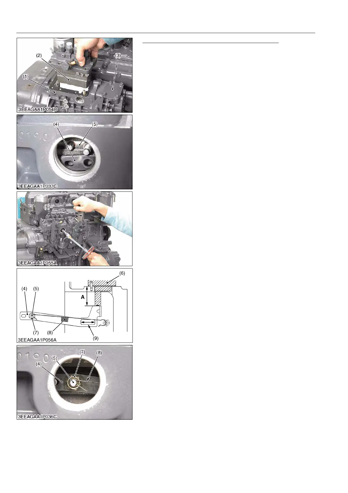
Installing Procedure of Injection Pump Assembly
1. Install the fuel injection pump assembly (2) in its unit (1), and
tighten the mounting screws and nuts.
2. Hook the governor connecting rod (4) to the rack pin of the
injection pump assembly (2).
3. Tighten the mounting screws and nuts with the specified torque,
not to slide off the governor connecting rod (4) from the rack pin.
4. Remove the top cover (3) and place the service jig (6) to the
hole of the fuel injection pump unit (1). (See page G-54.)
5. Make sure the permanent magnet at the tip of the service jig is
attracted to the governor connecting rod (4).
6. Slightly tighten the lock nut (7) of the governor connecting rod
(4).
7. Holding down the service jig (6) by hand, tighten up the lock nut
(7) to the specified torque.
8. Hook the start spring (8) to the rack pin (5).
(To be continued)
(1) Fuel Injection Pump Unit
(2) Fuel Injection Pump Assembly
(3) Top Cover
(4) Governor Connecting Rod
(5) Rack Pin
(6) Service Jig
(7) Lock Nut
(8) Start Spring
(9) Sliding Point between Governor
Fork Lever and Governor
Connecting Rod
A: 27.95 to 28.05 mm
(1.100 to 1.104 in.)