ENGINE
M6040, M7040, WSM
1-S60
(Continued)
(When reassembling)
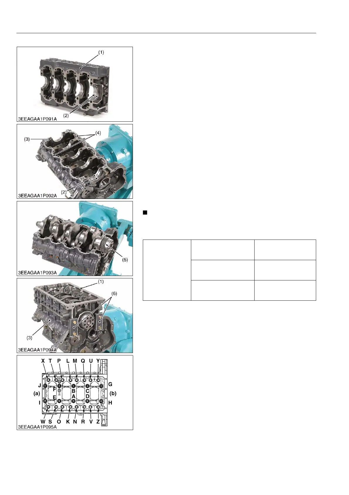
• Make sure the crankcase 1 (3) and 2 (1) are clean.
• Reassemble the thrust bearing (2), with the oil groove facing
outside, into both flywheel housing edge journal side of the
crankcase 1 (3) and 2 (1).
• Apply oil to the thrust bearing and set the crankshaft (5).
• Apply liquid gasket (4) (Three Bond 1217D) to the crankcase 1
as shown in the figure.
• Confirm that the liquid gasket coating surface is free of water,
dust and oil in order to maintain sealing effect.
• Carefully apply the adhesive evenly.
• Match the crankcase 1 (3) and 2 (1), referring to the flywheel
housing's contoured face.
• Tighten the crankcase 2 mounting screws "A to J" and the
crankcase 2 flange screws "K to Z" loosely after applying
engine oil.
• Tighten up the jig (6) to the specified torque same as the
flywheel housing screw. (See page G-50.) This helps to
minimize the level difference between the crankcase 1 and the
crankcase 2 (at the flywheel side). Possible gap must be
0.05 mm (0.0020 in.) or smaller.
• Tighten the crankcase 2 mounting screw and the crankcase 2
flange screw in the order of "A to Z".
• When mounting the adhesive-applied parts, take care to fit
them to the mating parts.
• Assemble the adhesive-applied parts within ten minutes.
9Y1210143ENS0085US0
Tightening torque
Crankcase 2 mounting
screw "A to J"
138 to 147 N·m
14.0 to 15.0 kgf·m
102 to 108 lbf·f
Crankcase 2 flange screw
"K to Z"
59 to 63 N·m
6.0 to 6.5 kgf·m
44 to 47 lbf·ft
Flywheel housing mounting
screw
103 to 117 N·m
10.5 to 12.0 kgf·m
76.0 to 86.7 lbf·ft
(1) Crankcase 2
(2) Thrust Bearing
(3) Crankcase 1
(4) Liquid Gasket
(5) Crankshaft
(6) Jig
(a) Front Cover Side
(b) Flywheel Housing Side
A to J: Crankcase 2 Mounting Screw
K to Z: Crankcase 2 Flange Screw