ENGINE
M6040, M7040, WSM
1-S70
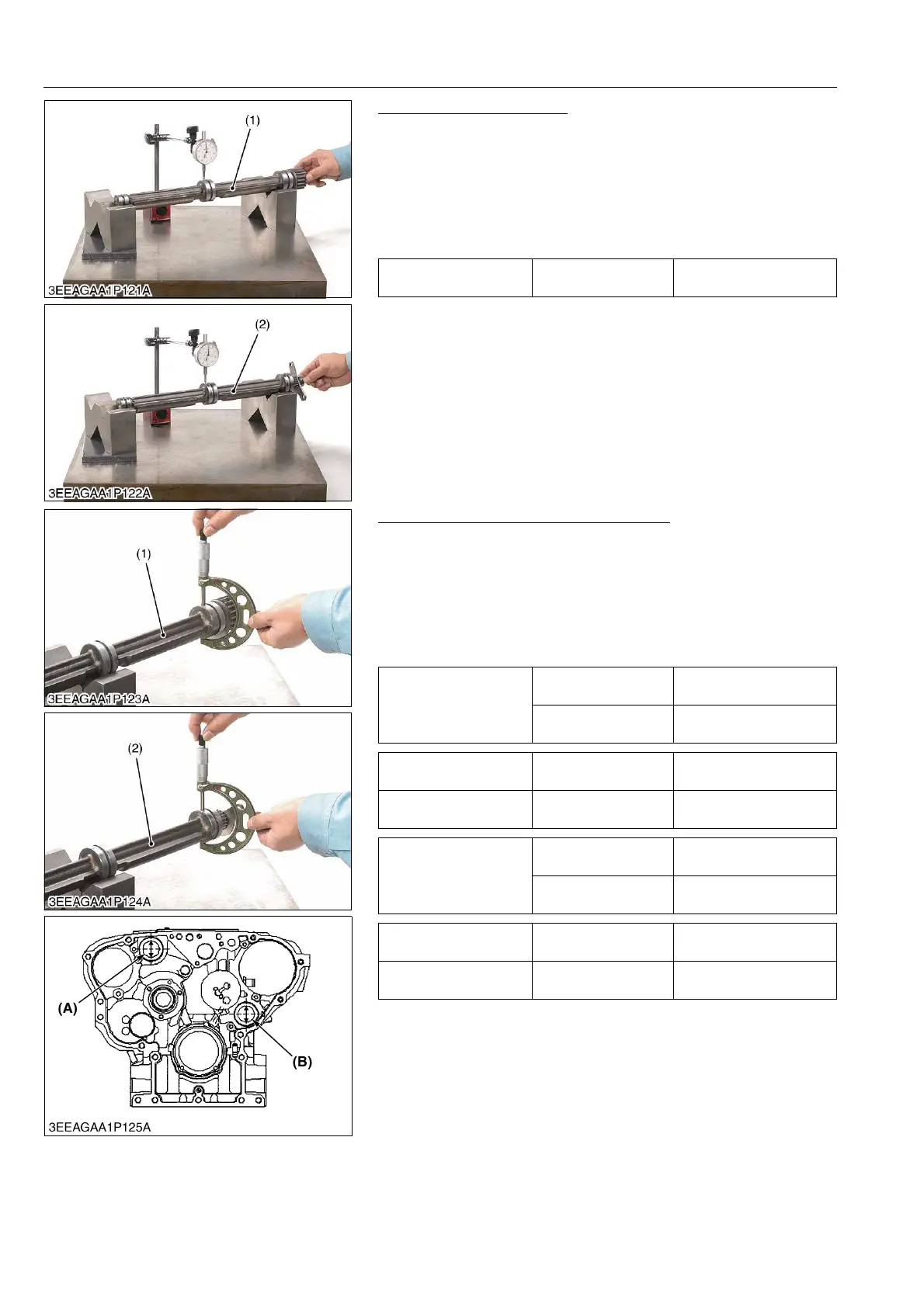
Balancer Shaft Alignment
1. Support the balancer shaft with V blocks on the surface plate
and set a dial indicator with its tip on the intermediate journal at
high angle.
2. Rotate the balancer shaft on the V block and get the
misalignment (half of the measurement value).
3. If the misalignment exceeds the allowable limit, replace the
balancer shaft.
9Y1210143ENS0111US0
Oil Clearance of Balancer Shaft Journal
1. Measure the balancer shaft journal O.D. with an outside
micrometer.
2. Measure the cylinder block bore I.D. (A), (B) for balancer shaft
with an inside micrometer.
3. If the clearance exceeds the allowable limit, replace the
balancer shaft bearing. If it still exceeds the allowable limit,
replace also the balancer shaft.
9Y1210143ENS0112US0
Balancer shaft 1, 2
alignment
Allowable limit
0.02 mm
0.0008 in.
(1) Balancer Shaft 1 (2) Balancer Shaft 2
Oil clearance of
balancer shaft 1 journal
Factory specification
0.060 to 0.146 mm
0.0024 to 0.0057 in.
Allowable limit
0.2 mm
0.0079 in.
Balancer shaft 1 journal
O.D.
Factory specification
48.934 to 48.950 mm
1.9265 to 1.9272 in.
Balancer shaft 1 bearing
I.D. (A)
Factory specification
49.010 to 49.080 mm
1.9295 to 1.9323 in.
Oil clearance of
balancer shaft 2 journal
Factory specification
0.050 to 0.136 mm
0.0020 to 0.0054 in.
Allowable limit
0.2 mm
0.0079 in.
Balancer shaft 1 journal
O.D.
Factory specification
48.934 to 48.950 mm
1.9265 to 1.9272 in.
Balancer shaft 1 bearing
I.D. (B)
Factory specification
49.000 to 49.070 mm
1.9291 to 1.9319 in.
(1) Balancer Shaft 1
(2) Balancer Shaft 2
(A) Balancer Shaft 1 Bearing I.D.
(B) Balancer Shaft 2 Bearing I.D.