ENGINE
M6040, M7040, WSM
1-S69
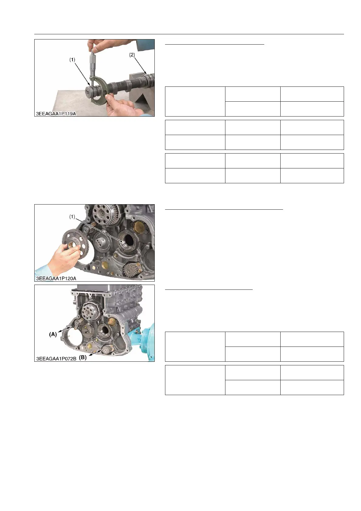
Oil Clearance of Camshaft Journal
1. Measure the camshaft journal O.D. with an outside micrometer.
2. Measure the cylinder block bore I.D. for camshaft with an inside
micrometer.
3. If the clearance exceeds the allowable limit, replace the
camshaft.
9Y1210143ENS0108US0
Replacing Camshaft Cover (If necessary)
1. Remove the used camshaft cover and clean the hole.
2. Install the new camshaft cover (1) until bumping using camshaft
cover replacing tool. (See page G-45.)
9Y1210143ENS0109US0
Balancer Shaft Side Clearance
1. Set a dial indicator with tip on the balancer shaft.
2. Measure the side clearance by moving the balancer shaft to the
front and rear.
3. If the measurement exceeds the allowable limit, replace the
balancer shaft.
9Y1210143ENS0110US0
Oil clearance of
camshaft journal
Factory specification
0.050 to 0.091 mm
0.0020 to 0.0036 in.
Allowable limit
0.15 mm
0.0059 in.
Camshaft journal 1 O.D. Factory specification
34.034 to 34.050 mm
1.3399 to 1.3406 in.
Camshaft block bore 1
I.D.
Factory specification
35.000 to 35.025 mm
1.3780 to 1.3789 in.
Camshaft journal 2 O.D. Factory specification
43.934 to 43.950 mm
1.7297 to 1.7303 in.
Camshaft block bore 2
I.D.
Factory specification
44.000 to 44.025 mm
1.7323 to 1.7333 in.
(1) Camshaft Journal 1 (2) Camshaft Journal 2
(1) Camshaft Cover
Side clearance of
balancer shaft 1
Factory specification
0.070 to 0.220 mm
0.0028 to 0.0087 in.
Allowable limit
0.3 mm
0.0118 in.
Side clearance of
balancer shaft 2
Factory specification
0.070 to 0.320 mm
0.0028 to 0.0126 in.
Allowable limit
0.3 mm
0.0118 in.
(A) Side Clearance of
Balancer Shaft 2
(B) Side Clearance of
Balancer Shaft 1