HYDRAULIC SYSTEM
M6040, M7040, WSM
8-S25
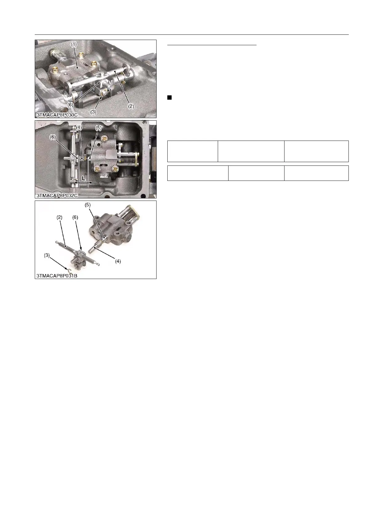
Control Valve and Spool Lever
1. Remove the control valve mounting screws.
2. Remove the E-shaped stopper (3).
3. Take out the control valve (1) and spool lever (2).
(When reassembling)
• Be sure to fix the O-rings to the control valve and apply grease
to them.
• Do not disassemble the spool joint 1 (4) from the spool (5)
unless necessary.
If disassembled due to unavoidable reasons, record the
installation length "L" of the spool joint 3 (6) and spool (5).
When reassembling, be sure to make to a former length.
9Y1210143HYS0029US0
Tightening torque
Control valve mounting
screw
19.6 to 23.5 N·m
2.0 to 2.4 kgf·m
14.5 to 17.4 lbf·ft
Length "L" Reference value
24.5 to 25.0 mm
0.9646 to 0.9842 in.
(1) Control Valve
(2) Spool Lever
(3) E-shaped Stopper
(4) Spool Joint 1
(5) Spool
(6) Spool Joint 3