Chapter 10 Distance to Fault Operation
Distance to fault calibration
9102 Handheld Spectrum Analyzer Software version 5.31
169
3 Push the Cal. Cab. Dielec. key to enter the dielectric constant,
r
.
See Table 15 for the dielectric of cables delivered by Aeroflex for
this purpose.
4 Push the
Cal. Cab. Length key to enter the length of the calibration
cable. See Table 15 for the length of cables delivered by Aeroflex
for this purpose.
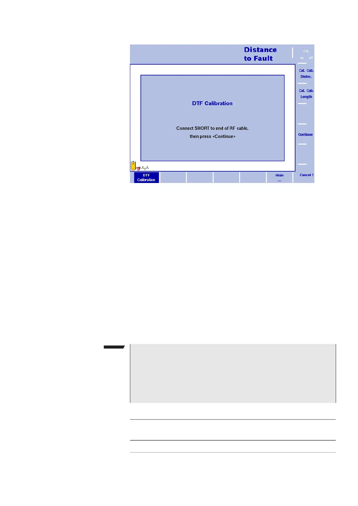
5 The 9102 will guide you through the calibration process by
onscreen messages as shown in Figure 48. When prompted as
shown connect the calibration set to the test port extension cable
and press
Continue. You can abort the calibration process by
pressing the
Cancel ! softkey.
6 When calibration is completed the Distance to Fault main menu will
be displayed again. On the left handside of the results display the
calibration icon will now be displayed in green and read “Calib’d“
(Calibrated).
Figure 48 Distance to fault Calibration menu
NOTE
When performing a number of measurements it can be necessary to
repeat the calibration process due to temperature changes etc. This
is a regular behaviour. Furthermore, if you change the frequency
band, calibration has to be repeated. As soon as calibration is nec-
essary the 9102 will inform you by displaying the red “Calibrate“
icon.
Table 15 Parameters for Aeroflex-supplied cables
Cable description
Dielectric
constant
r
Length
Test port extension cable 2.3 1.0 m (3.3 ft)