OPERATOR’S MANUAL
CMA-9000 FLIGHT MANAGEMENT SYSTEM
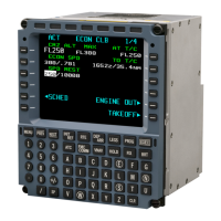
Crew have entered the takeoff speeds and the takeoff FLEX temperature. Thrust reduction height and
acceleration height display the default values extracted from the Policy File.
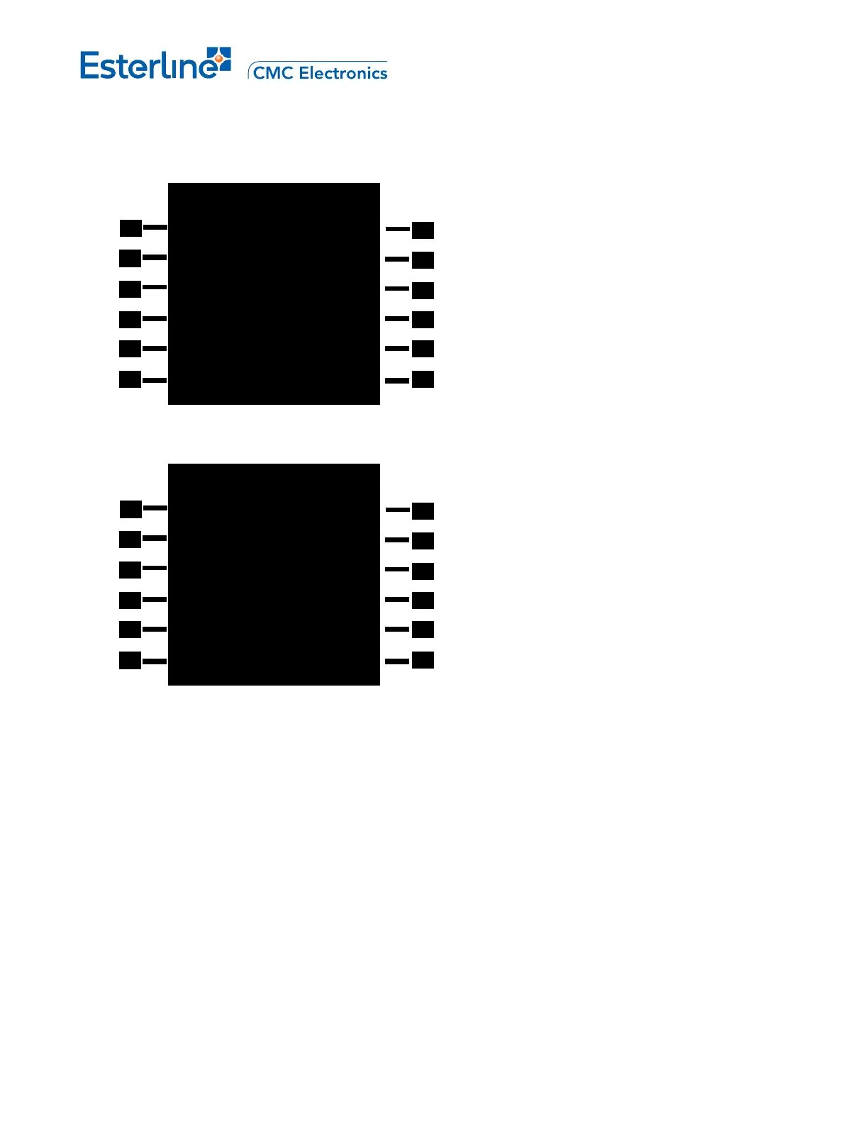
Crew have entered V
1
speed but did not enter V
R
and V
2
; the crew entered a takeoff thrust de-rate of 15%, the
thrust reduction and acceleration height.
TAKEOFF REF 1/1
V1 -FLEX
140KT F44ºC
DERATE
VR
143KT 3000FT
ACCEL HT
V2
146KT 1500FT
THR RED HT
FLAP RETR
144KT
SLAT RET GREEN DOT R
185KT 200KT
<INIT/REF ROUTE>
TAKEOFF REF 1/1
V1 DERATE LEX
140KT D15%
-F
VR ACCEL HT
KT 3200FT
V2 THR RED HT
KT 1600FT
FLAP RETR
146KT
SLAT RETR GREEN DOT
185KT
200KT
<INIT/REF ROUTE>
V
1
[1L]:
V
R
[2L]:
V
2
[3L]:
On ground, allows crew entry and display of the takeoff decision speed (V
1
), takeoff rotation speed (V
R
) and
takeoff safety speed (V
2
) respectively. All takeoff speed entries must respect the following rule: V
1
<= V
R
< V
2.
FLAP RETR (4L):
SLAT RETR (5L):
GREEN DOT (5R):
These data fields present to the crew the following speeds as received from the Stall Warning System (SWS):
• Minimum Speed for flap retraction
• Minimum Speed for slat retraction
• Green dot Speed
Page RRJ-A-5
August 17, 2010