Section 5: The Patchbay
Euphonix CS3000/2000 Operation Manual 5 - 5
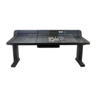
Rear of Audio Tower showing
multi-way cables connected
to patchbays
The Euphonix
Patchbay System
Control
Master
CH. 1-4
CH. 5-8
CH. 9-12
CH. 13-16
CH. 17-20
CH. 21-24
CH. 25-28
CH 1 - 4
CH 5 - 8
CH 9 - 12
CH 13 - 16
CH 17 - 20
CH 21 - 24
CH 25 - 28
MASTER
Audio Tower Rear View
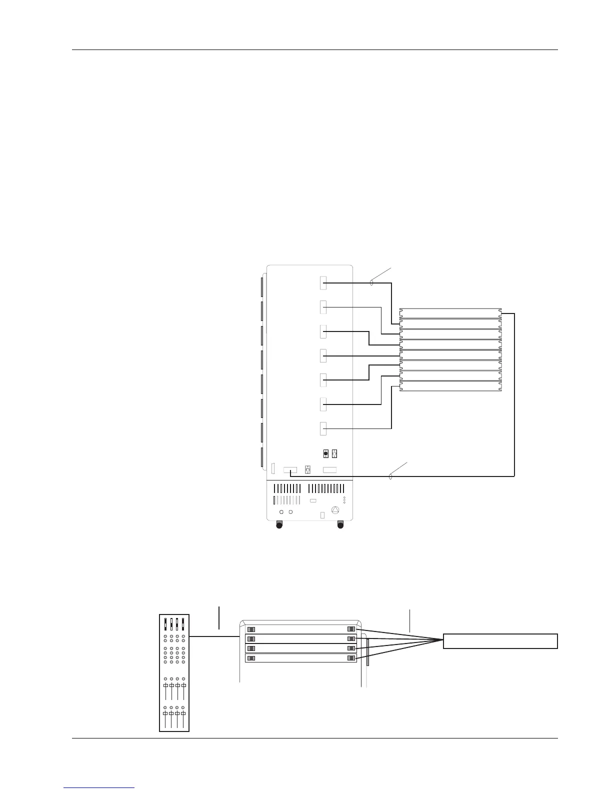
Suggested Patchbay Layout
4 channels of audio per 90-way Elco snake
Master audio snake
Channel Patchbay 1-4
I/O
Controller
Audio
harness
Control
harness
Channel 1
Channel 2
Channel 3
Channel 4
Audio Tower
The easiest way to navigate to the appropriate jack when you look at the
patchbay is by understanding the patchbay’s basic organization from the
perspective of system modularity. The Euphonix patchbay system is designed
for convenient expansion when adding more channels of audio to the console.
As already mentioned, one Audio Tower can accommodate up to 28 channels
(56 faders). At the rear of the Tower, you will see a vertical row of seven 90-
way Elco connectors. Each one of these Elcos carries 4 channels of audio in
and out of the Tower, connected via an audio snake to one channel patchbay.
An additional 90-way Elco near the bottom of the Tower provides the master
audio via an audio snake to the Master patchbay. One Audio Tower requires a
maximum of 7 Channel patchbays and one Master patchbay. All Elco connec-
tors have gold-plated pins to ensure long lasting, low-resistance connections.
Each I/O control module addresses 4 channels of audio, and every group of 4
channels is accessed via 1 patchbay. The control/interface scheme is: