M2
M1 L1
L3
L2
L4
Aux Buses
1 - 8
ST1
ST2 Solo
MT Buses
DCA
R / even
DCA
L / odd
6:1
6:1
ST1-L
ST1-R
ST2-L
ST2-R
AFL-R
AFL-L
PFL-R
PFL-L
1
2
3
4
5
6
7
8
9
10
11
12
DCA
R / even
DCA
L / odd
6:1
6:1
ST1-L
ST1-R
ST2-L
ST2-R
AFL-R
AFL-L
PFL-R
PFL-L
1
2
3
4
5
6
7
8
9
10
11
12
D
DCA
A1
A2
A3
A4
A5
A6
A7
A8
6:1
6:1
C
DCA
A1
A2
A3
A4
A5
A6
A7
A8
B
DCA
A1
A2
A3
A4
A5
A6
A7
A8
6:1
Automated Aux Sends
A1
A2
A3
A4
A5
A6
A7
A8
6:1
A
DCA
6:1
6:1
6:1
6:1
6:1
CMB
6:1
Lo - Med - Hi
Lo - Med - Hi
CMB/M1
L4/Bus
PWR
PAD
PWR
PAD
M2/Bus
Bus Summing Amp
1-24 (bus 1 to channel1 etc...)
∑
EQ1
EQ2
M1
M2
L3
L4
L1
L2
Dir 1
Dir 2
Dir 2
Out 1
Out 2
Out 3
Dynamic Range
Dynamic Range
Processor/Emulator
Processor/Emulator
ES108
ES108
A
A
MIDI
Key Mon
2
4
6
9
12
15
21
30
MIDI
Key Mon
2
4
6
9
12
15
21
30
MIDI
Key Mon
2
4
6
9
12
15
21
30
MIDI
Key Mon
2
4
6
9
12
15
21
30
MIDI
Key Mon
2
4
6
9
12
15
21
30
MIDI
Key Mon
2
4
6
9
12
15
21
30
MIDI
Key Mon
2
4
6
9
12
15
21
30
MIDI
Key Mon
2
4
6
9
12
15
21
30
ES108A Dynamics
Out 3 & CMB
Bus/M1 switch
M2
L2
L4
MT
CMB
LFR
UFR
M1
L1
L3
CMB
MT
LFL
UFL
Right
Meter
Left
Meter
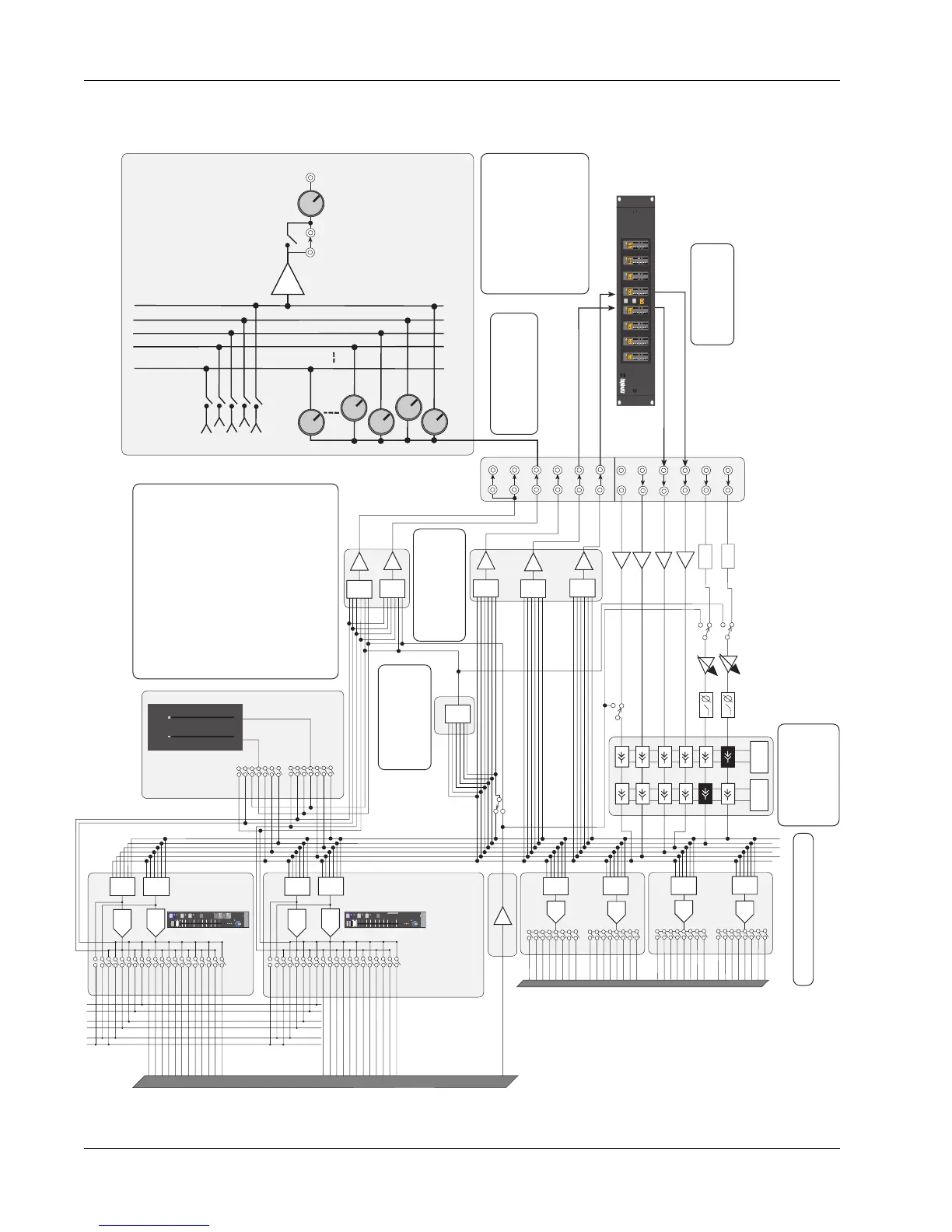
The Out 3 pre fader output is
typically used as a third insert
send paired with L3.
In the current revision of channel
electronics, the Group Bus output
can be sent to Out 3 in place of
the M1 signal freeing up the Dir 1
and Dir 2 outputs for use as post
fader feeds to the Cube.
The Dirs can be configured
as dedicated mono or stereo
post fader feeds from a lower
or upper fader.
Dynamics
Each optional dynamics
provides variable hi-
pass & low-pass filters.
Assignable EQ
Two per channel. These
EQ can remain as
individual, be cascaded
to produce an 8 band
EQ, or stereo linked.
Source - Mode - Assign
Combiner
Allows any combination
of pre fader inputs to be
sent to DIR1, DIR2 and
back into M1 input.
Dir 1 & Dir 2
Assignable Direct Outputs
Available selections are:
Group Bus Output
This is the default assignment. Dir2 typically
feeds the multitrack recorder inputs.
Bus # equals channel #.
Post Lower Fader, left and/or right.
Post Upper Fader, left and/or right.
These post fader selections are commonly used
to feed the Cube main inputs for Multi-Format
Panning, additional aux sends, or mix minus
feeds.
Combiner
Provides additional pre-fader output.
OUT 1, 2, 3
Assignable pre fader
outputs - Can be used as
insert sends or general
purpose pre-fader outputs.
1
1
2
3
448
Assignable Aux
Sends
from every fader
up to 48
Via the Cube
2
3
4
48
∑
Bus Insert
IN/OUT
Bus
Master
1 of 48
possible
Direct Bus
Inject Inputs
with link switch
The console aux
buses can be linked
into the Cube buses
integrating the two
Aux systems into one
Input
EQ•Dyn
BUS
Grp
1
2
L
R
ON
AFL
PFL
DIR
ST1
M1 M2
L1 L2
L3 L4
ovld
PAN BAL
ST2
Input
LL
F
Grp
BUS
ON
AFL
PFL
1
3
5
7
9
11
2
4
6
8
10
12
DIR
ST1
ST2
ovld
PAN BAL
M1
L1 L2
L3 L4
1
3
5
7
9
11
2
4
6
8
10
12
M2
U L
B
F
6
3
3
6
12
33
6
3
3
6
12
33
0 0
0
6
12
18
24
30
36
42
48
60
0
6
12
18
24
30
36
42
48
60