Section 5: The Patchbay
Euphonix CS3000/2000 Operation Manual 5 - 9
Normalling the
Multitrack Returns
Multitrack returns are generally normalled across the console to either Mic
Input 2 (M2) or Line Input 4 (L4) since M2 and L4 have bus/tape switching. The
M2 inputs offer input gain trim and phase reverse for each tape return. These
functions are also selectively available for each L4 input if the signal is routed
through the combiner into the M1 input of that channel. If you decide to
normal all multitrack returns to M2, you lose the ability to normal linked stereo
sources to M1 and M2. The choice of whether to normal multitrack returns to
M2 or L4 inputs depends on the needs of a particular studio.
Another option is to normal each multitrack return into both M2 and L4. During
tracking this leaves M1 & M2 free for stereo sources to the upper fader as the
lower fader acts as a multitrack monitor fader fed from L4. During mixdown,
the lower fader can source the multitrack from M2 with level trim to the input.
Multitrack recorder inputs are typically connected to the patchbay Dir2 outputs
as the multitrack bus feed. Since there are two (multed) Dir2 feeds from each
channel:
• Up to 48 tracks can be accommodated by the 24 multitrack buses
• The second Dir2 feed may also be used as an additional post-fader
output to feed other devices (e.g., the Euphonix Audio CUBE).
The default setting for Dir1 and Dir2 is “Bus”, however it can be changed from
the Dir Assignment menu. See the Tutorial section.
L1, L2, and L3 are typically used with Out1, Out2, and Out3 respectively as
insert send/return pairs, and are often used for normalled insertion of the
ES108A Dynamics processors. If the system is supplied with 1 dynamics
processor per channel, for example, each processor is normalled into send/
return pair Out1/L1 (Dyn1). If the system is supplied with 2 dynamics proces-
sors per channel, Dyn1 is normalled into Out1/L1 and Dyn2 into Out2/L2. This
configuration still allows the user the flexibility of an extra insert (Out3/L3)
that can be used for the upper or lower fader.
See the ES108A Dynamics Installation and Service Manual for wiring configu-
ration diagrams for various Euphonix mixing systems.
Audio CUBE cabling is shipped from the Euphonix factory in one of the follow-
ing configurations:
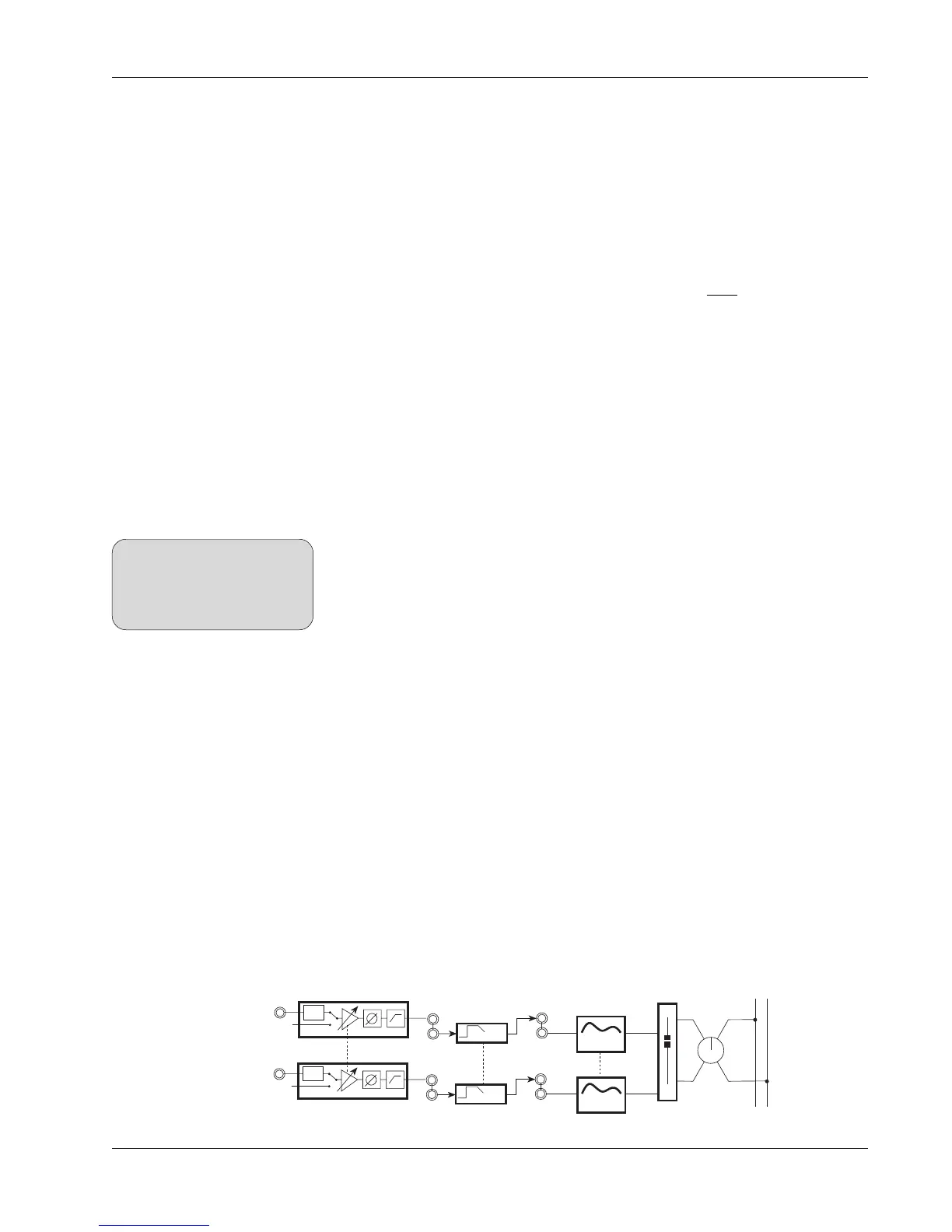
Normalling the
Multitrack Sends
PWR
LF
PWR
STEREO 1 BUS
L R
M1
M2
BAL
4 Band EQ
4 Band EQ
Stereo Links
EQ2
EQ1
DYN
OUT2
L2
DYN
OUT1
L1
DYN 1
DYN 2
Normalling the
Dynamics
SIDE NOTE:
In systems with 2 channel CUBE
cables, it may be more practical
to use Out3 as the MT Bus send
to the recorder.