Section 9: Dynamics
9 - 4 Euphonix CS3000/2000 Operation Manual
gate and compressor, or expander and filters. Complete control over dynamics
parameters include all standard controls such as attack, release, ratio, hold
time and compressor threshold characteristic.
Inverse compression
(shown as
a ratio with minus sign; where the dynamic range of the output is less than the
input, but the output level decreases as the input level increases) is also
possible.
The variable filters, which can be individually set to low pass, high pass, band
pass, or notch, can be placed in the main signal path to augment the EQ. Each
processor can be hard bypassed with a software-controlled relay to take it out
of circuit when not in use. Individual elements such as the compressor, gate,
or filters may be switched off. New software updates on EPROM provide
additional programs to extend the capability of the unit even after installation.
These processors may be wired into any channel on the console using the
insert points (Out1/Line1, Out2/Line2, or Out3/Line3). Whenever possible, the
processors should be assigned and wired in order (for 2-per-channel operation,
processors 1 and 2 in channel 1, processors 3 and 4 in channel 2, etc.).
For simplicity of operation and for the sake of uniformity between systems,
Euphonix suggests that for one mono processor per channel, the processor
should be wired between Out 1 (to the main input of the dynamics) and Line 1
(from the output of the dynamics). For a pair of dynamics per channel, they
should be wired between Out 1/Line1 for the first processor and Out2/Line2
for the second processor.
If enough units are available, fit at least one dynamics per channel to save on
repatching. A 48-fader system (24 channels) should be fitted with a minimum
of 24 processors (three ES108A units). Before using the dynamics, make sure
you examine and know how they are wired. An External Key input to each
processor is available and may be wired to an additional patchbay. See the
ES108A Installation and Service Manual for more information, including MIDI
control wiring and ELCO connector pinouts.
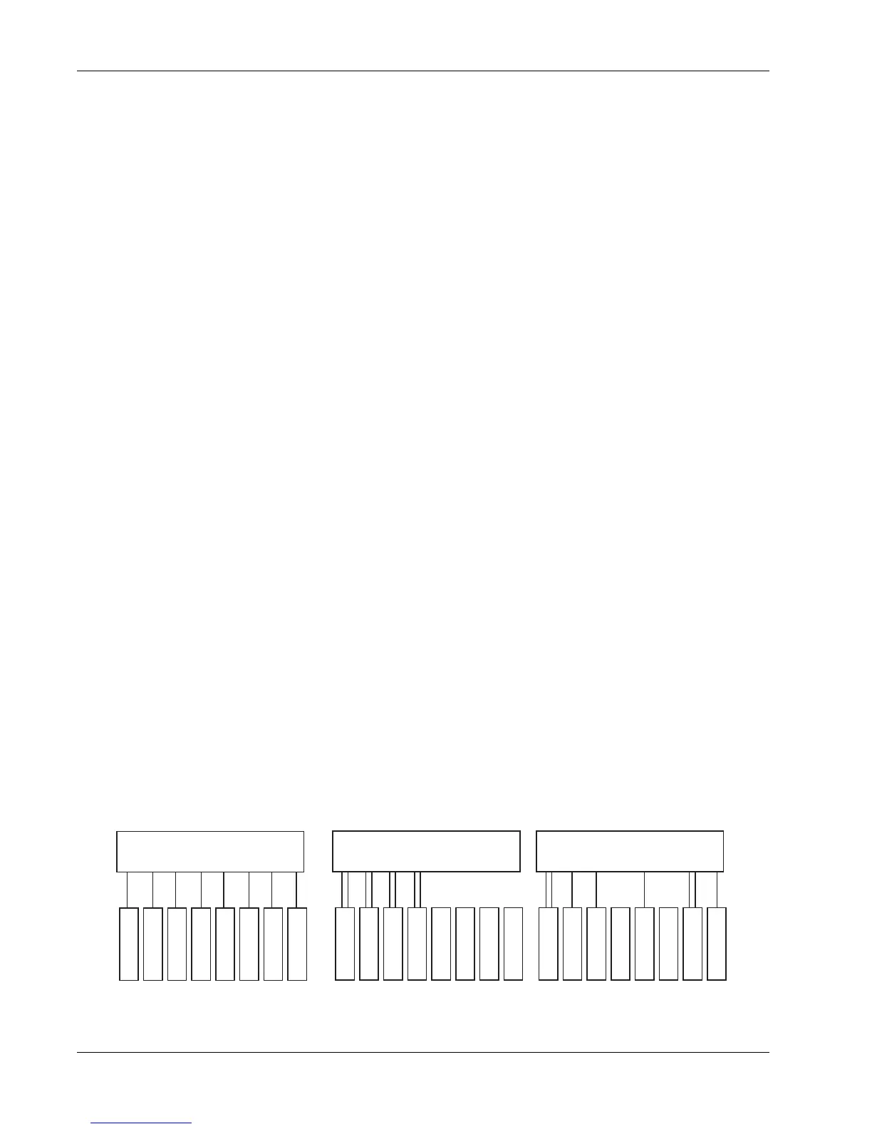
An ES108A unit can be wired into the patchbay in one of three ways:
ES108A Wiring
The software configuration must be set to reflect the wiring of the hardware
for proper operation. (See Dynamics Software Setup later in this section)
Two dynamics per channel
ES108A
8 Processors
Channel 1
Channel 2
Channel 3
Channel 4
Channel 5
Channel 6
Channel 7
Channel 8
ES108A
8 Processors
Channel 1
Channel 2
Channel 3
Channel 4
Channel 5
Channel 6
Channel 7
Channel 8
ES108A
8 Processors
Channel 1
Channel 2
Channel 3
Channel 4
Channel 5
Channel 6
Channel 7
Channel 8
One dynamics per channel Custom wiring