Section 4: Tutorial
Euphonix CS3000/2000 Operation Manual 4 - 5
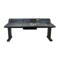
In this exercise we will construct a stereo signal path to route a stereo source
through the console and out to the monitors.
Begin this exercise from a “Default” (or zeroed) console, and create a new title
in which to store your Tutorial work. Patch your sound source into the M1 &
M2 inputs of a channel. We will use channel 16 for this example. A compact
disc makes a good sound source because it’s usually 45 minutes of uninter-
rupted signal. Start playing the sound source you are going to use now.
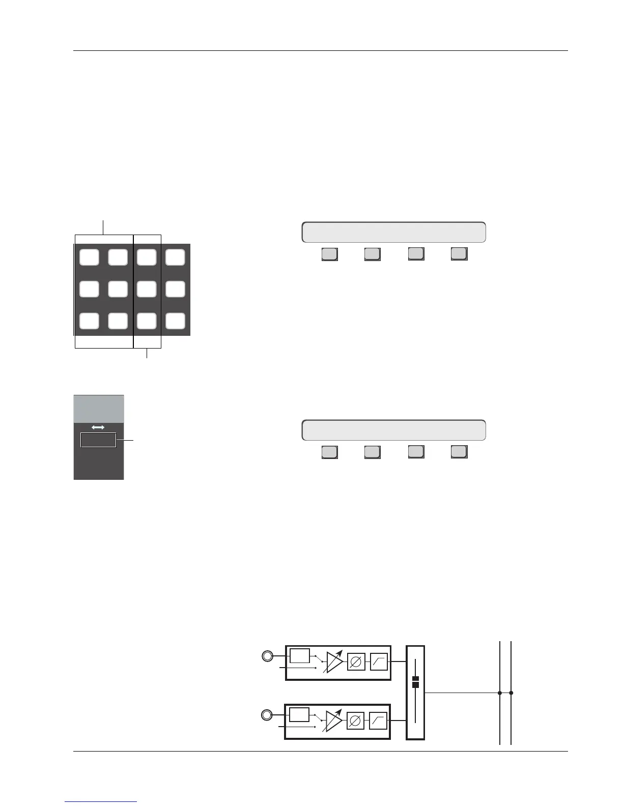
Press channel 16’s lower fader block key. Notice that the menu in the Smart-
Display has changed to this:
F3F1 F2 F4
This means that you now have control of channel 16’s lower fader from the
DSC. Select the source by pressing the [M1] & [M2] Dedicated keys. Notice
that when you press these keys, the M1 & M2 Source LEDs light in channel
16’s lower fader block. If you press [M1] again, notice that it toggles the M1
source off. In this case, only the M2 input is feeding the fader. Press [M1]
again to re-select it, checking the final routing by looking at the Source display
next to the pan/bal control of the fader block as seen in the diagram to the
left. Select [L1] through [L4] in the same way. Selections will appear in the
SmartDisplay:
F3F1 F2 F4
While in the SRC menu, pressing the DSC [Clr] key clears all input selections.
Clear the selections and select only M1 & M2.
Next we will select an assignment to send the fader output to a desired
destination. In our example we will assign to the ST1 bus. Press the DSC [ST1]
Dedicated key. You will now see that ST1 Assign LED lights in 16’s lower fader
block. Try deselecting ST1 by pressing the [ST1] Dedicated key again, and
selecting [ST2] as the destination. ST2 is a completely separate stereo bus
with its own master fader, insert and patch points. Re-select only ST1.
The signal path we have set up now looks like this:
Exercise 1
Stereo Source/
Stereo Fader/
Stereo Bus/
Monitor
Source
16LF–> SRC MODE ASGN
SRC–> M1 M2 L1 L2 L3 L4
Assign
M1 M2 DIR All
aux
L1 L2 ST1 All
upper
L3 L4 ST2 All
lower
Assign Dedicated keys
Source Dedicated keys
Input
M1 M2
L1 L2
L3 L4
M1 & M2 only
are sourced from
lower fader
PWR
LF
PWR
STEREO 1 BUS
L R
M1
M2