Section 4: Tutorial
4 - 4 Euphonix CS3000/2000 Operation Manual
The channel strip is organized into 7 channel blocks. Each block has its associ-
ated attention key located within the block. These are the Channel block,
Universal Input blocks (M1 & M2), Aux Send blocks (A/B & C/D), Upper Fader
block, and Lower Fader block. Take a moment to identify the individual blocks
of a channel strip on your console using the diagram on page 1-6.
When you press a block attention key, you can control that block via the
Master Control Panel and the DSC. You will then be able to configure the
signal path of that block directly from the DSC.
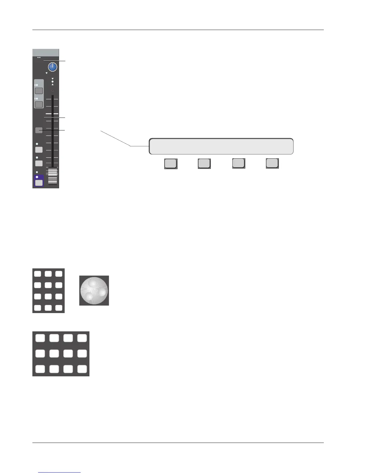
Press the lower fader block attention key on channel 16. You will notice that
the SmartDisplay on the Master Control Panel shows the following menu:
F3F1 F2 F4
“16LF” means that the Master Control Panel now controls channel 16’s lower
fader block. The arrow indicates that the routing for that block is described in
the menus to the right. We have to select the input source (SRC) for the fader,
the mode (MODE) of the fader, and the output assignment (ASGN) for the
fader’s signal. Source and assign selection can be done directly from the DSC
Dedicated Keys section. Sources and assignments are indicated on every block
by hidden-til-lit displays for easy reference.
Modes are used to select how signals are routed and combined through the
two DCAs of each fader or aux send block. Mode selections can be selected
directly from the DSC Numeric keypad or by scrolling through modes using the
SpinKnob. Until you gain familiarity with the options, press SmartDisplay key
[F3] (MODE) and use the SpinKnob to find the mode you need. If you are
familiar with the modes, you can enter the corresponding mode number, then
press the DSC [Enter] key. A complete listing of available modes to each
block can be found in the Appendix section.
Source selections can be any of the console channel strip’s 6 inputs. They are
M1, M2, L1, L2, L3, and L4. M1 and M2 are commonly thought of as micro-
phone preamplifiers, but are actually universal input amplifiers (U.I.A.s) that
accept a wide range of levels and impedances. Each of these inputs is
equipped with phase reverse, high-pass filter, and phantom power. The DCA
for M1 can be used for the Combiner. L1 - L4 are simply non-variable, line-level
amplifiers. Both M2 and L4 inputs have the option of bus/tape switching.
Assignment selections are ST1, ST2, Multitrack group buses (24 from upper
fader only, or 12 from upper and lower faders depending on Audio Tower
jumper configuration - see technical manual for details), Direct Outputs (Dirs 1
& 2), and Aux buses 1 - 8 (from the aux blocks only).
16LF-> SRC MODE ASGN
Channel Blocks
Routing
Parameters
Source
Assign
M1 M2 DIR All
aux
L1 L2 ST1 All
upper
L3 L4 ST2 All
lower
DSC Source/Assign
Dedicated Keys
Input
EQ•Dyn
BUS
Grp
1
2
L
R
ON
AFL
PFL
DIR
ST1
M1 M2
L1 L2
L3 L4
ovld
PAN BAL
ST2
Assign Indicators
Source Indicators
Fader Block
Key
Mode
or
789
456
123
0 Enter Del