EQ2
EQ1
A
B
C
D
A1
A3
A5
A7
M1
M2
L3
L4
1
3
5
7
9
11
13
15
17
19
21
23
ST2 L
Solo L
2
4
6
8
10
12
14
16
18
20
22
24
6:1
ST1 L
ST2 R
Solo R
ST1 R
6:1
6:1
ST2 L
Solo L
ST1 L
ST2 R
Solo R
ST1 R
UF
LF
6:1
6:1
BUS
1-24
6:1
OUT1
L1
OUT2
L2
1
2
3
4
48
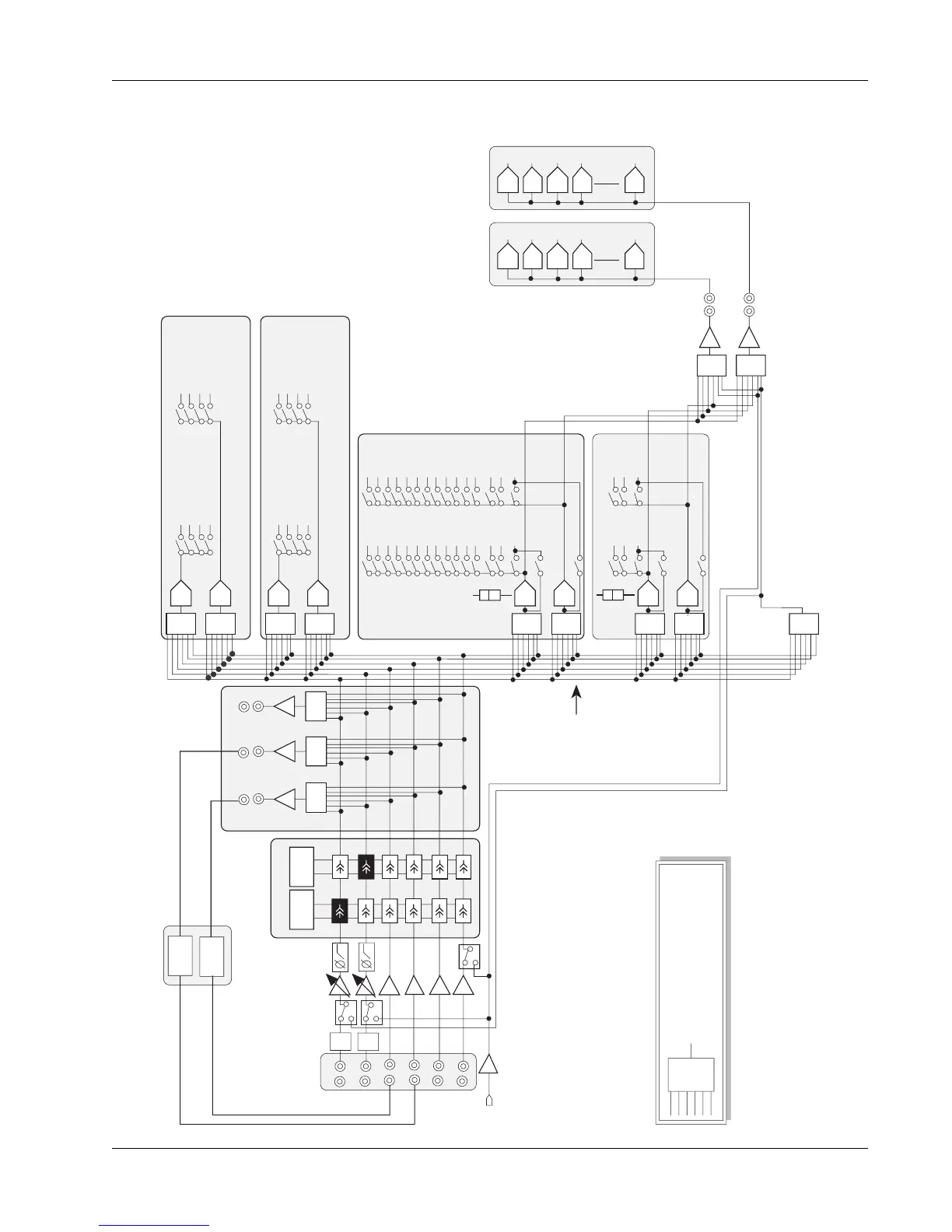
A & B Automated
Aux Sends
C & D Automated
Aux Sends
DCA
DCA
DCA
DCA
DCA
DCA
DCA
DCA
6:1
6:1
6:1
6:1
6:1
6:1
6:1
DIR 1 & DIR 2 source assignments are:
1- The group bus summing amp for feeding multitrack
recorders. This is the default assignment.
2- Post Lower or Upper Fader for feeding Cube inputs,
providing additional aux sends, mix minus feeds, and
Multi-Format buses as shown.
3- The Combiner, providing an additional pre-fader output.
PFL
PFL
PFL
PFL
DIR2
Bus Summing Amp
1-24 (Channel 1 picks up
bus 1 etc..)
A2
A4
A6
A8
Combiner: Allows any
combination of pre fader inputs
to be sent to DIR1, DIR2 and
back into M1 input
M1,M2
L1,L2,L3,L4
signals post
EQ &
Dynamics
M2 & L4
have
Bus/Input
switch
Dynamics
Each optional dynamics
provides variable hi-
pass & low-pass filters
Audio Cube
Optional
Multi-Format Buses
Additional
Aux Sends, Multi-Format mix
stems, Mix Minus feeds
From 4 to 48 buses
DYN2
DYN1
A1
A3
A5
A7
A2
A4
A6
A8
DIR1
6:1
OUT3
OUT 1, 2, 3
Can be used as insert sends
or general purpose pre-fader
direct outputs
1
2
3
4
48
M1 has
CMB/Input
switch
PWR
PAD
PWR
PAD
This symbol represents a six (6)
input selector/summing circuit.
It can select and sum any
combination of the inputs.
6:1
DCA
DCA
DCA
DCA
DCA
DCA
DCA
DCA
DCA
DCA