Section 4: Tutorial
Euphonix CS3000/2000 Operation Manual 4 - 25
This exercise looks at routing the signal (microphones, instruments, etc.) to the
multitrack recording system. We will route the input signal (in this case a
microphone), to the multitrack via the upper fader.
Make sure the monitor Level pots are turned down to avoid the possibility of
acoustic feedback. Plug a microphone into channel 1’s M1 patch point. Set up
the gain and phantom power by selecting the correct options from M1’s input
block (see Universal Input Amplifiers earlier in this section). Press channel 1’s
upper fader block key and select the [M1] input using the DSC Dedicated Keys.
This connects the microphone to the upper fader.
From the SRC menu, pressing [F2] will cycle the SmartDisplay menu through
the three setup menus, SRC, MODE, & ASGN. Go to the ASGN menu or just
press the [
+
Bus] key as a shortcut:
F3F1 F2 F4
You are being asked to select a multitrack bus. Enter the desired bus numbers
(1 and 2 for the sake of our exercise), from the numeric keypad and then press
Enter after each assignment. Observe the bus assignment area of channel 1’s
upper fader. You will see that the bus numbers you’ve assigned are lit. A more
expedient way to accomplish this is to use the DSC Channel Selection keys.
Make sure the up arrow located to the left of the Assignable Key is lit to
select the upper fader. Press the [Route] key to put the DSC Channel Selection
keys into Route mode. Press the desired keys to assign multitrack buses.
Press [F2] again to cycle to the MODE menu. If you have a mono source and
you intend to pan between a pair of multitrack buses, set the mode to “Mono
Pan”. If you have a mono source and you want to assign it to only one bus or
Exercise 4
Multitrack Routing
Assign
Source
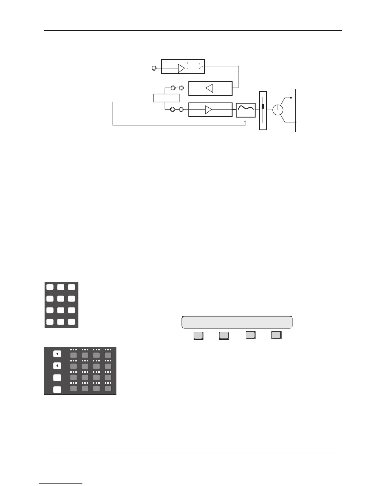
As with our stereo channel inserts from Exercise 2, the EQ is placed post-
insert point by sourcing the EQ from L3 rather than L4:
Mode
1UF->ASGN MT ?
DSC Channel Selection keys
REC
Slct
onln
REC
Slct
onln
REC
Slct
onln
Solo
Route
4
1613 14 15
!
1
@
2
#
3
$
4
Q W E
123
tab
25
shft
26
A
27
S
28
D
37
spc
38
Z
39
X
40
C
or
DSC Keypad
If you have assigned an insert loop, either complete the loop using patch
cables, insert a processor device, or un-assign the inserts before continuing.
This concludes Exercise 3. Make sure to save your work in a new snapshot
location.
L4
Line Input 4
BUS
Line Input 3
Dynamics
Processor
L3
OUT3
Line Output 3
LF
STEREO 1 BUS
L R
PAN
4 Band EQ
Post-insert EQ