Section 4: Tutorial
4 - 26 Euphonix CS3000/2000 Operation Manual
equally to two buses, select Mono mode. For this experiment choose “Mono
Pan” mode. The M1 signal is now assigned via the upper fader and pan, to
multitrack buses 1 and 2. This follows standard conventions of an I/O strip.
The signal is sent down buses 1 & 2 to the associated bus summing amps. As
in conventional in-line consoles, the summing amp resides in the I/O of the
same number, (i.e., bus amp 1 resides in channel 1, bus 2 in channel 2, etc.).
From there the signal is sent out DIR1 & DIR2 of the channel. DIR1 & DIR2
output assignments default to the multitrack bus output. There will be more
information on DIRs later in this section.
If the multitrack machine is switched to input, you will be able to monitor the
signal by bringing up lower faders 1 & 2, as they should already be on
(unmuted) and routed to ST1.
For certain signal routing situations, the MT bus can be sent from Out3. This is
useful when the Dir 1 & Dir 2 connectors must be used to feed a 2/channel
Cube for example. Another example may be to obtain a stereo post fader
direct feed using Dir 1/2.
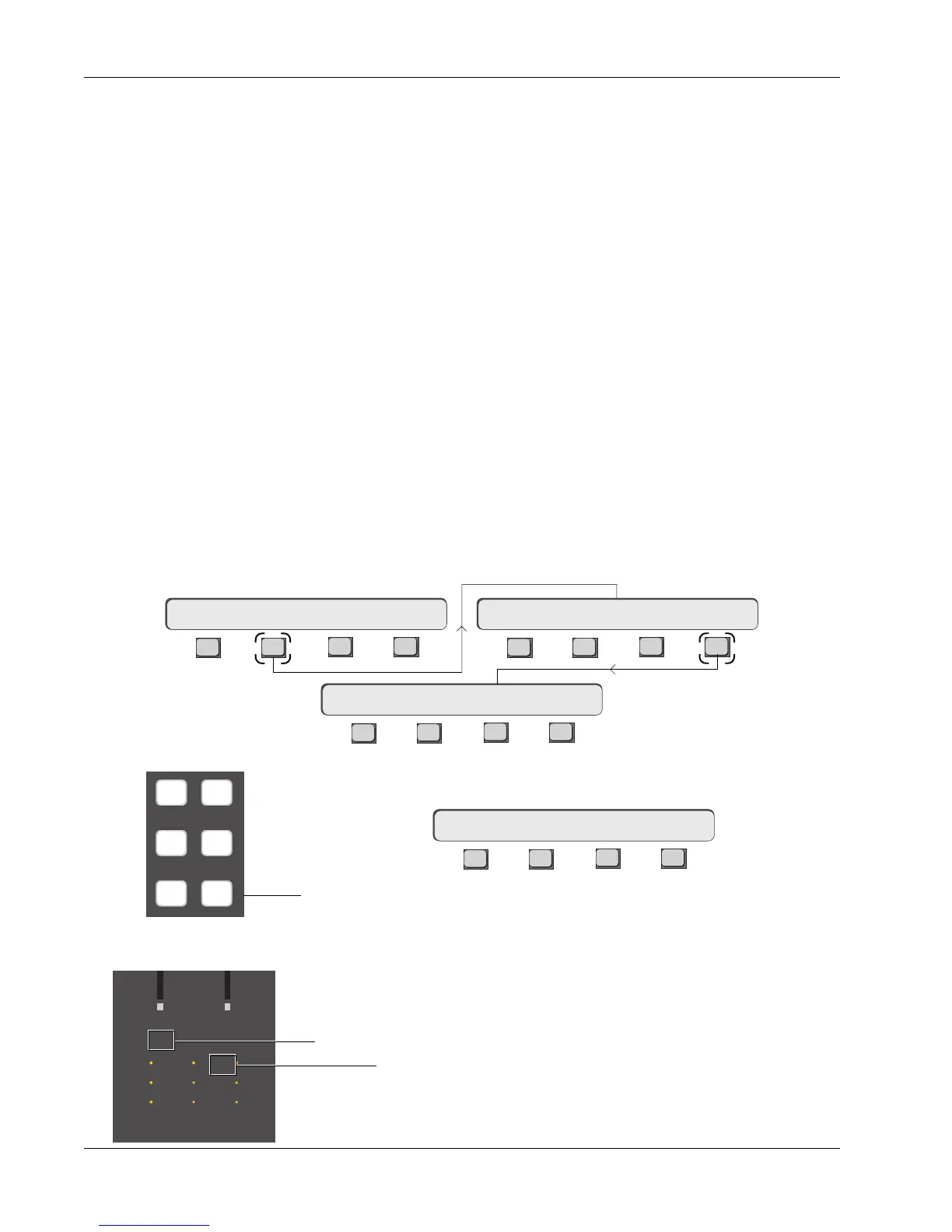
To set the Out3/MT routing, press the channel attention key at the top of the
channel, [F2] (OUTs) and then [F4] (OUT3):
Bus Summing Amps
MT Bus to Out3
Now press the [
+
Bus] or [F3] keys to assign the MT bus to Out3.
F3F1 F2 F4
If M1 had been previously set as the Out3 source, MT replaces it. You may
also use the DSC Source Assign keys to assign additional sources to Out3.
When MT is selected to the Out3 bus, the M1 Out3 channel I/O source matrix
LED remains lit (for both M1 and MT assignments) along with the B LED (MT
for the CS2000).
1CH->OUT3 MT
F3F1 F2 F4
F3F1 F2 F4
F3F1 F2 F4
16CH-> OUT1 OUT2 OUT316CH-> OUTs METER Route
16CH->OUT3 ?
33
M
L
L
M
L
L
M
L
L
33
60
Out 1 Out 2 Out 3
60
12
12
34
12
12
34
12
12
34
UL
B
F
Out3, M1 designation
Indicates MT selected as Out3 source
M1 M2
L1 L2
L3 L4