Section 4: Tutorial
4 - 20 Euphonix CS3000/2000 Operation Manual
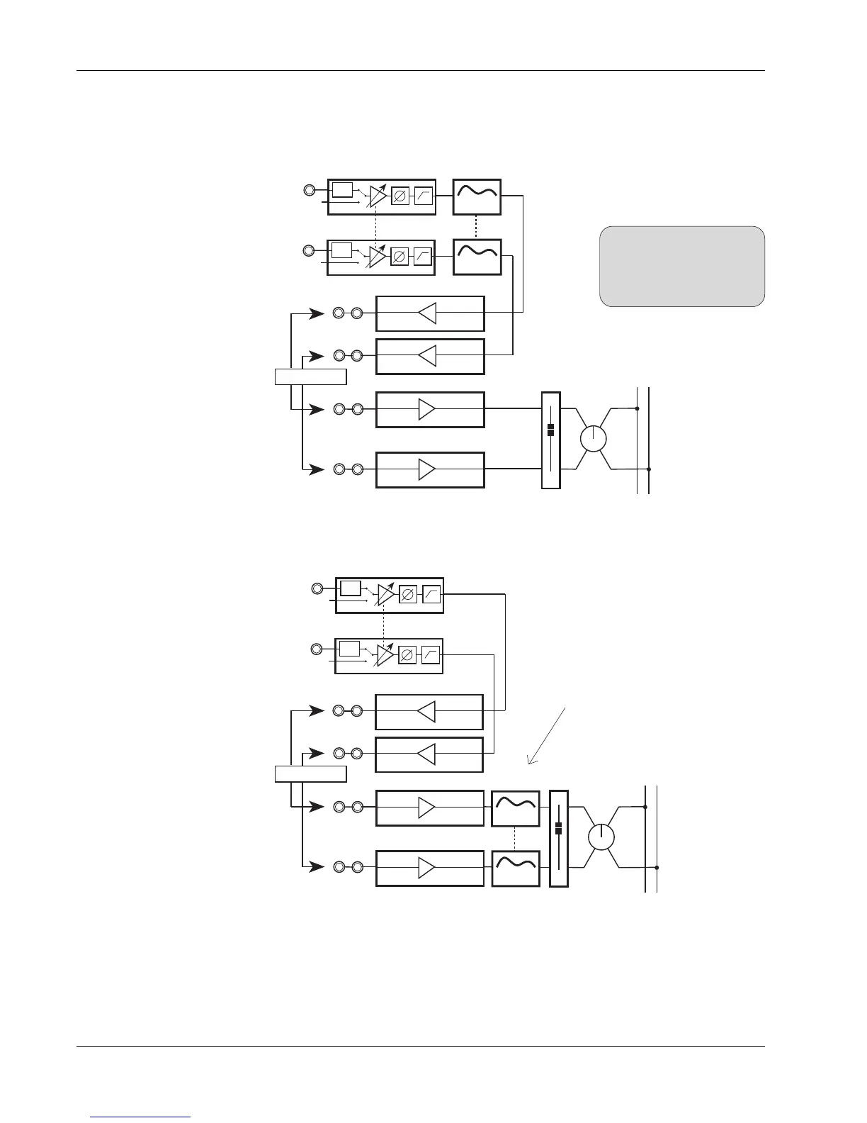
Insert Diagrams,
Pre- & Post-EQ
At this point, you should patch an external device, such as a stereo limiter,
across the Out1/L1 and Out2/L2 insert points. The signal flow looks like this:
To put the EQ post-insert point, change the EQ source from M1 & M2 to L1 &
L2 to produce this signal path:
SIDE NOTE:
When an EQ and an Out are
both assigned to the same
source, the EQ always comes
first in the signal path.
To bypass the insert point, select M1 and M2 rather than L1 & L2 as the
sources for both the EQ and the fader (this can be done with one button press
using the SnapShot Recall system).
This concludes Exercise 2.
Insert send
patch points
Insert return
patch points
PWR
PWR
M1
M2
4 Band EQ
4 Band EQ
Stereo Links
EQ2
EQ1
LF
STEREO 1 BUS
L R
OUT2
OUT1
BAL
Line Input 2
Line Input 1
L2
L1
Stereo Limiter
PWR
PWR
M1
M2
Stereo Links
LF
STEREO 1 BUS
L R
OUT2
OUT1
BAL
Line Input 2
Line Input 1
4 Band EQ
4 Band EQ
EQ2
EQ1
L2
L1
EQ1 & EQ2 placed after L1 & L2
instead of M1 & M2
Insert send
patch points
Insert return
patch points
Stereo Limiter