Section 1: Introduction
Euphonix CS3000/2000 Operation Manual 1 - 9
-
DIR
+
Bus
can be used as a reference guide. However, we strongly suggest that you go
through the Tutorial, which uses examples to illustrate how the system
operates. Section 2 explains the file structure and how to save your work.
Subsequent sections then take you through operation of the whole console
using examples and exercises. Section 7 covers the automation system in
detail. Section 9 describes the operation of the software-integrated Euphonix
ES108A Dynamics unit. Section 10 describes the operation of the software-
integrated Euphonix Audio Cube and various available multi-format bus
options and functions. The fastest way to become a fully-functional Euphonix
user is to go through the Tutorial section while sitting in front of the console.
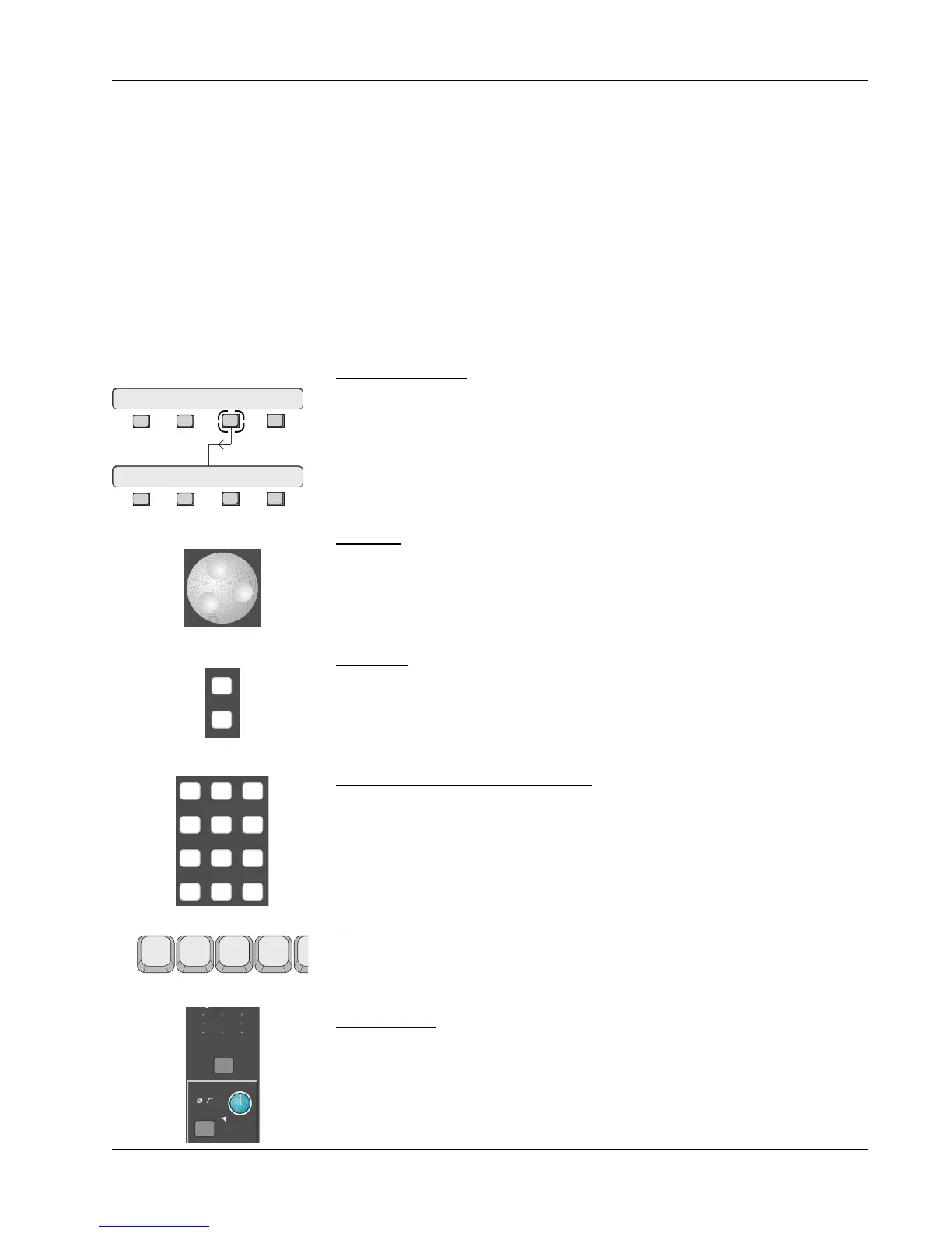
The following are used to illustrate various concepts throughout this manual:
SmartDisplay menu. These icons are used repeatedly throughout this text to
show how to navigate through the console menu trees. Lines connecting one
SmartDisplay to another indicate movement through the menus by pressing
one of the four Special Function keys. In the example to the left, the F3 key
should be pushed in the upper menu to go to the lower menu.
SpinKnob. This icon is used to show that you can use the SpinKnob on the DSC
to cycle through available menu options in the SmartDisplay and through lists
on the screen display.
+ & – keys. These keys are often used in conjunction with or instead of the
SpinKnob to cycle through menu options and lists. These icons are an example
of how the keys on the console are represented throughout this text.
Master Control Panel Numeric keypad. This keypad is used to make menu
selections in the SmartDisplay. Note the Enter key, which often must be
pressed to confirm a numerically keyed entry. Don’t confuse this with the
keypad on a QWERTY keyboard.
Function keys on the QWERTY keyboard. These are used to choose some
system functions that only require occasional access.
Console blocks. The functional control blocks that make up the Mix Controller
surface are sometimes represented by icons such as this one, which shows
the M1 Input block with gain pot, block attention key, and indicators.
This Manual
Useful Symbols
F1 F2 F3 F4
789
456
123
0 Enter Del
M
L
L
M
L
L
M
L
L
M1
Out 1 Out 2 Out 3
1 2
1 2
3 4
1 2
1 2
3 4
1 2
1 2
3 4
ovld
Pwr
Pad
F3F1 F2 F4
Setup Snap Auto Grps
F3F1 F2 F4
File Pass Tplate Punch