17.2.1.3 I/O panel connectors
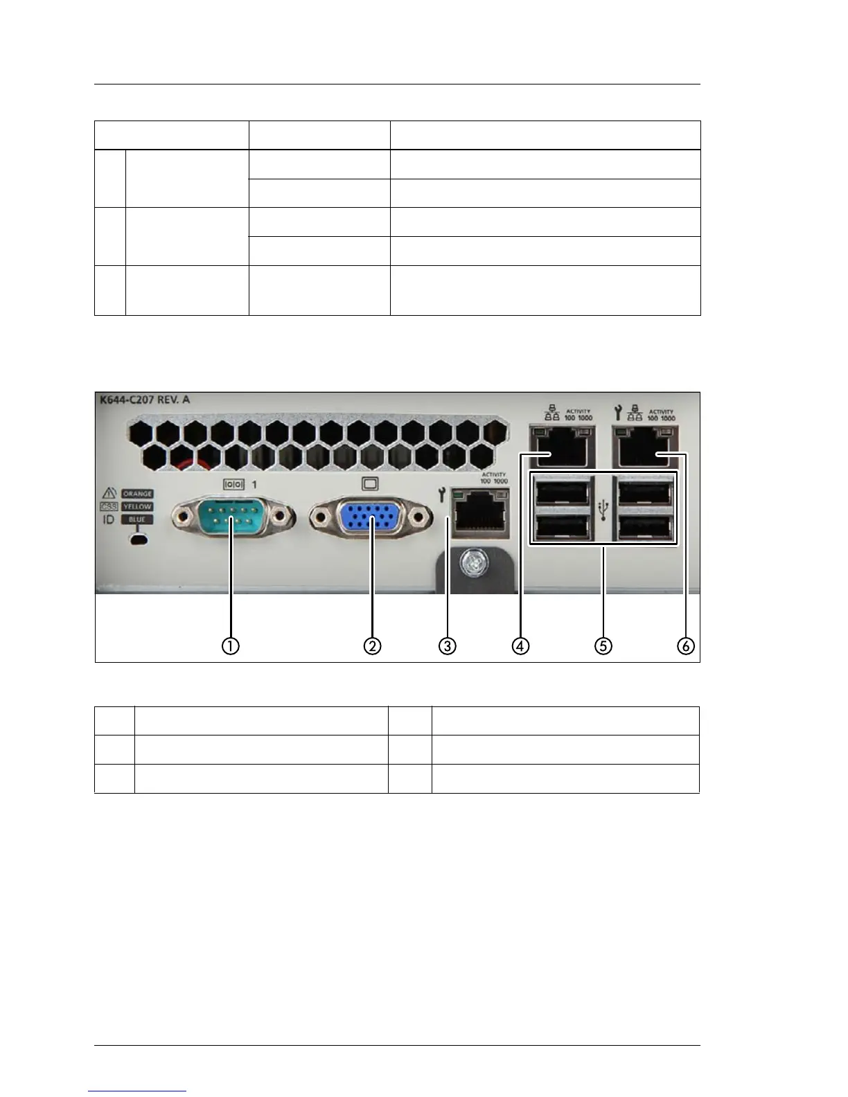
Figure 318: I/O panel connectors
Depending on BIOS settings, the shared LAN connector may also be used as
a management LAN connector. For further information, please refer to the
corresponding BIOS Setup Utility reference manual.
The serial connector COM1 can be used as default interface or to communicate
with the iRMC S4.
N Fans
off fan running
orange on fan failure
O Battery
off battery running
orange on battery failure
P
Memory
module
orange on at least one memory module faulty
1 Serial connector COM1 4 Standard LAN connector (LAN1)
2 Video connector (VGA) 5 4 USB connectors
3 Management LAN connector 6 Shared LAN connector (LAN2)
Indicator Status Description

 Loading...