Chapter 8 Mandatory Setting for Motor Drive and Test Run
8-2-4
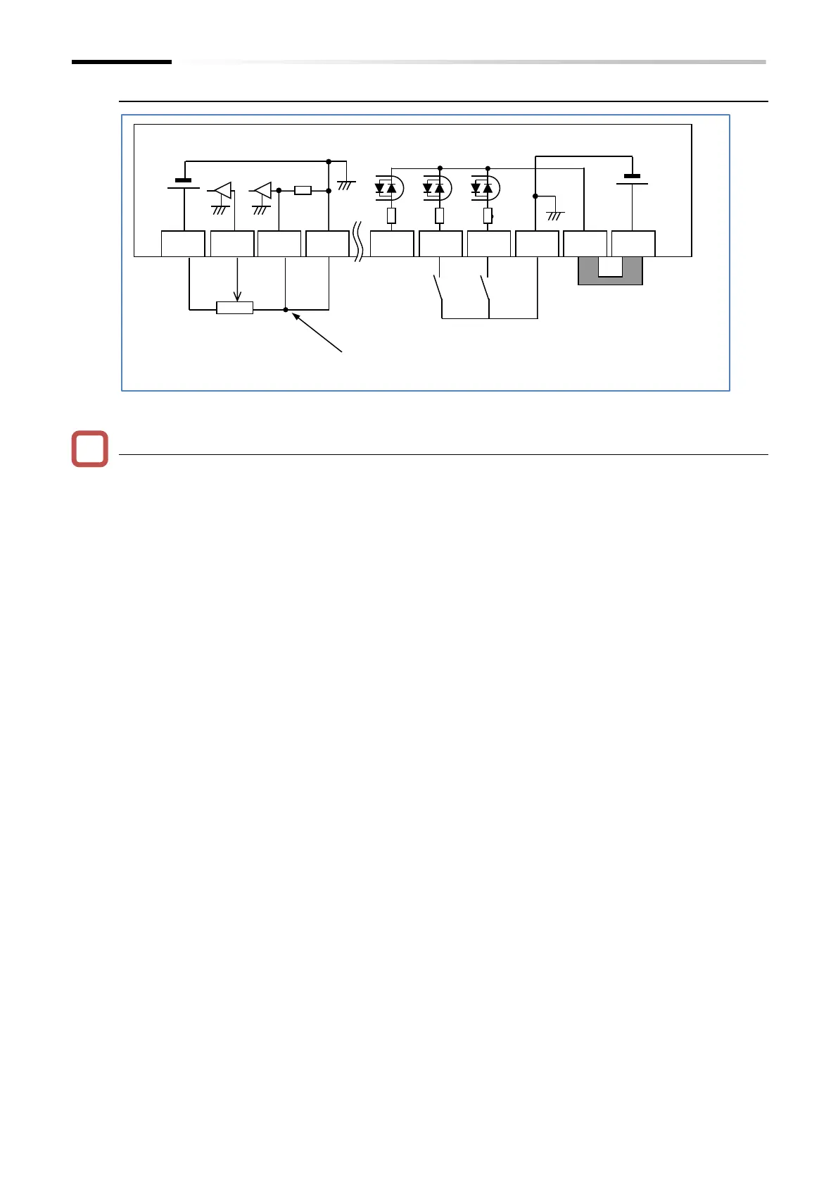
■ Example of control terminal wiring
■ Confirmation during test run with no load
Confirm that the operation direction of the machine is correct, that the machine operates
smoothly without abnormal noise or vibration, and that the machine operates normally without
abnormal noise or vibration even if the frequency command or operation direction is changed.
Confirm that there is no trip during acceleration/deceleration and that the rotation speed and
frequency meter are correct.
Check "Output current monitor [d002]" and "DC bus voltage monitor [d102]" to make sure that
the current/ voltage values have enough margin to trip.
If "Overcurrent error [E01] to [E04]" or "Overvoltage error [E07]" occurs during test run, try
increasing the acceleration/ deceleration time.
Refer to "Chapter 15 Tips/FAQ/Troubleshooting" for more information about tripping and
troubleshooting.
*1 When the [AT] input terminal is not assigned,
short-circuit the current input [Ai2] terminal with L.

 Loading...


