Chapter 9 Inverter Functions
9-2-5
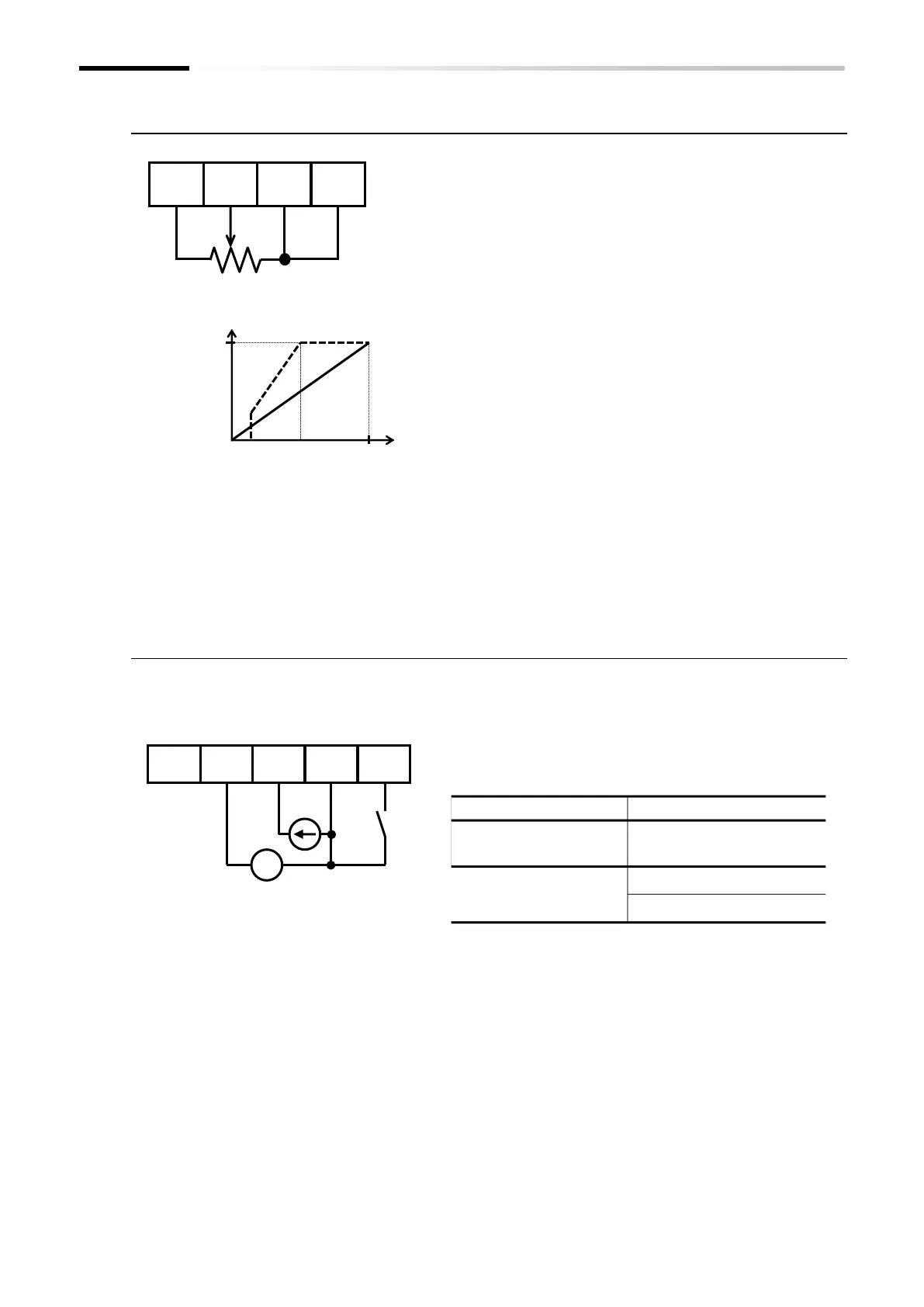
■ (Example 1) Voltage input from [Ai1] (using a potentiometer), no [AT] terminal
assignment
■ (Example 2) Using the [AT] terminal to switch between [Ai1] voltage input and
[Ai2] current input
If the [AT] terminal is not assigned, [Ai1] + [Ai2] will act as the
As shown in the figure to the left, when issuing a frequency
command consisting of a 0 to 10 VDC voltage input from the
[Ai1] terminal, short-circuit the [Ai2] terminal to the [L]
terminal to prevent it from being exposed to electrical noise.
(* When using current input from the [Ai2] terminal, be
sure to short-circuit the [Ai1] terminal to the [L]
terminal.)
The default setting is 0 to 10 VDC and 4 to 20 mA analog
input to represent values from zero to the maximum frequency
(Hz). (Straight line on the graph shown on the left.)
As represented by the dashed line on the graph shown on the
left, you can use the analog input start/end function to
change the relationship between the analog input value and
the frequency command value. For details, refer to "9.15.3
Adjusting the Analog Input".
Potentiometer (1 to 2 kΩ)
Control circuit terminal block
[Ai1] terminal 0 VDC
[Ai2] terminal 4 mA
Connect a device such as an analog output module with a 0
to 10 VDC voltage input to [Ai1] or 4 to 20 mA current input
Assign the [AT] input terminal to one of the input terminals
[1] to [7] and set the "[AT] selection [A005]" parameter to
"00".
Any parameter from
[C001] to [C007]
Control circuit terminal block
The default state is 0 to 10 VDC and 4 to 20 mA analog input to represent values from zero to the
You can use the analog input start/end function to change the relationship between the analog input
value and the frequency command value. For details, refer to "9.15.3 Adjusting the Analog Input".

 Loading...


