Chapter 9 Inverter Functions
9-2-6
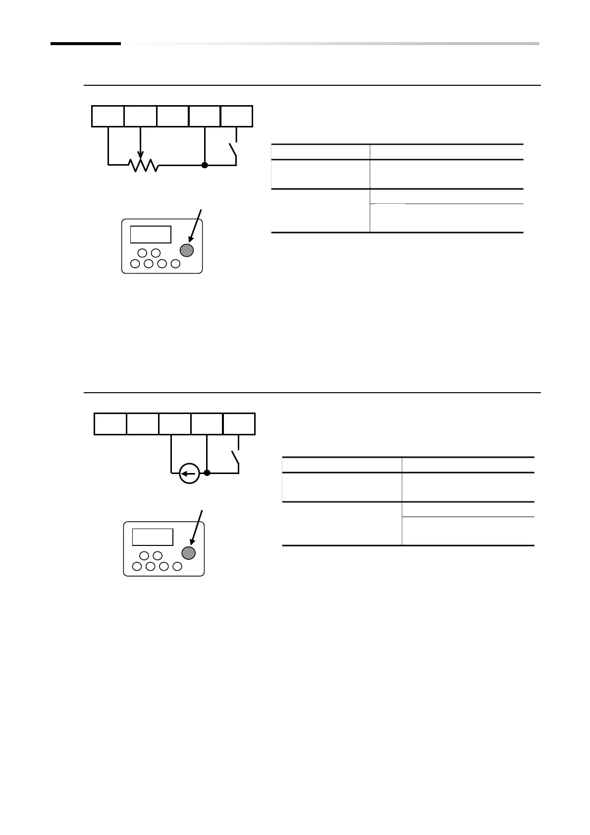
■ (Example 3) Using the [AT] terminal to switch between [Ai1] voltage input and
the remote operator potentiometer [POT]
■ (Example 4) Using the [AT] terminal to switch between [Ai2] current input and
the remote operator potentiometer [POT]
Remote operator with potentiometer
OPE-SR/OPE-SRmini
Potentiometer (1 to 2 kΩ)
Control circuit terminal block
Connect a device such as an analog output module with a voltage
operating range of 0 to 10 VDC to [Ai1].
Assign the [AT] input terminal to one of the input terminals [1] to
[7] and set the "[AT] selection [A005]" parameter to "02".
Any parameter from
[C001] to [C007]
ON: Remote operator
potentiometer [POT]
The default state is 0 to 10 VDC to represent values from zero to
the maximum frequency (Hz).
For more details regarding how to change the relationship
between the analog input value and the frequency command
value, refer to "9.15.3 Adjusting the Analog Input".
Connect a device such as an analog output module with a
current operating range of 4 to 20 mA to [Ai2].
Assign the [AT] input terminal to one of the input terminals [1]
to [7] and set the "[AT] selection [A005]" parameter to "03".
Any parameter from
[C001] to [C007]
ON: Remote operator
potentiometer [POT]
The default state is 4 to 20 mA to represent values from zero to
the maximum frequency (Hz).
For more details regarding how to change the relationship
between the analog input value and the frequency command
value, refer to "9.15.3 Adjusting the Analog Input".
Remote operator with potentiometer
OPE-SR/OPE-SRmini
Control circuit terminal block

 Loading...


