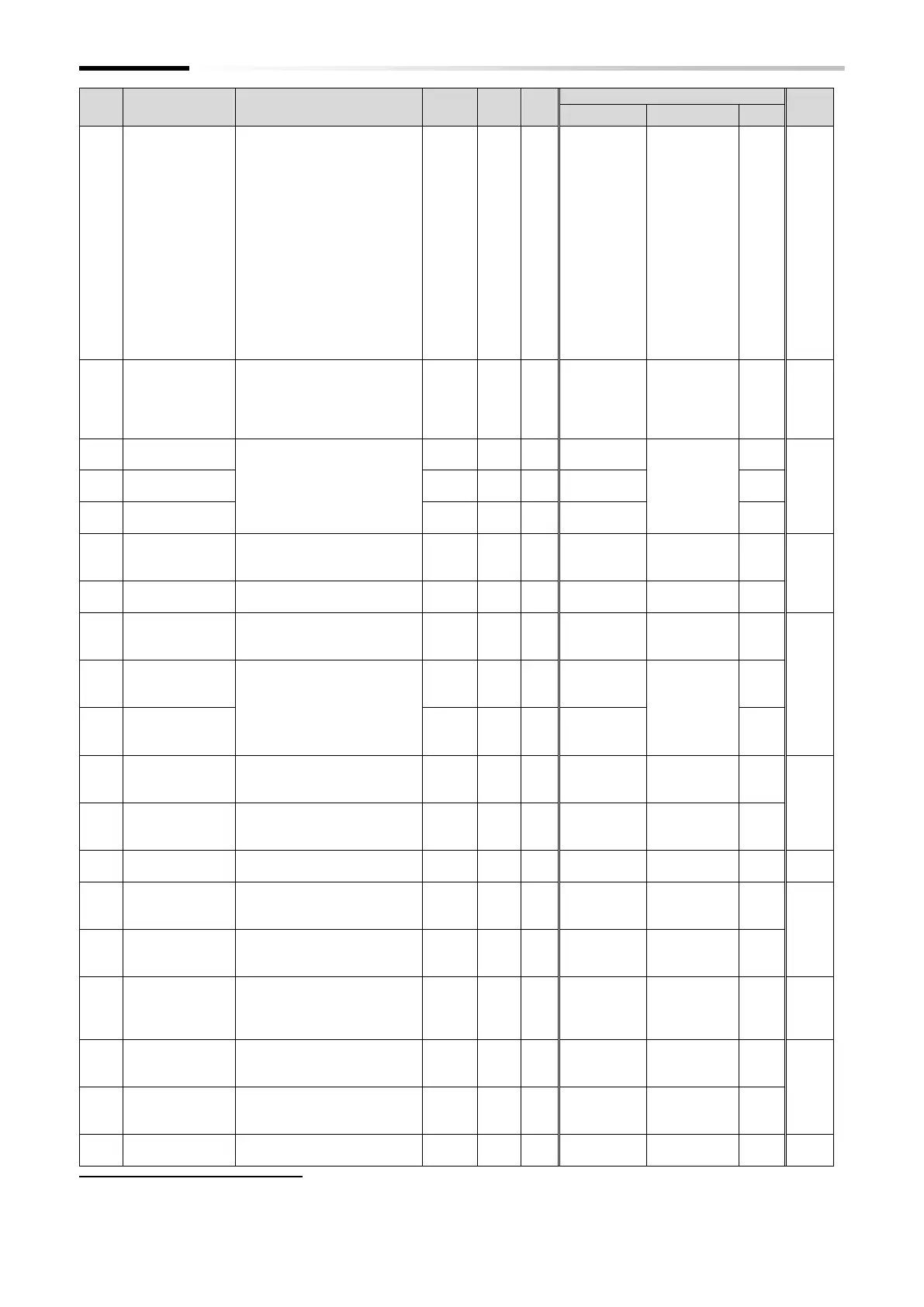
Chapter 18 List of Parameters/Modbus Coil/Register Numbers
18-2-20
[Ao1] Output
monitor selection
(Analog output
monitor)
00: Output frequency
01: Output current
02: Output Torque
(Sensorless vector control)
04: Output voltage
05: Input power
06: Electronic thermal load
ratio
07: LAD frequency
10: Cooling fin temperature
11: Output torque (signed)
(Sensorless vector control)
13: EzSQ General-purpose
analog output YA1
16: Option
0 to 2, 4 to 7,
10,
11, 13, 16
[Ao2] Output
reference value
(at digital output
current monitor)
(0.20 to 2.00) × Rated
current (A)
(When [C027] is set to "Digital
current monitor", set the current to
be output at 1440Hz.)
200 to 2000 (ND)
200 to 1500 (LD)
Output terminal
[11] active state
00: NO: Normally Open
01: NC: Normally Closed
Output terminal
[12] active state
Output terminal
[AL] active state
Low current
signal output
mode selection
00: Enable during running
01: Enable only during
constant speed
Low current
detection level
(0.00 to 2.00) × Rated
current (A)
Overload signal
output mode
selection
00: Enable during running
01: Enable only during
constant speed
Overload warning
level, 1st-motor
(0.0 to 2.00) × Rated current
(A)
Overload warning
level, 2nd-motor
Arrival frequency
during
acceleration
Arrival frequency
during
deceleration
Arrival frequency
2 during
acceleration
Arrival frequency
2 during
deceleration
Pulse input/
monitor output
scale convert
gain
Turn-off level for
the PID feedback
compare signal
Turn-on level for
the PID feedback
compare signal
Over/ Under-
torque selection
00: Over-torque
01: Under-torque
*2. 100% of the set value means the rated current of the WJ-C1.

 Loading...


