A.1.3 Comparison of Control Circuit Terminal Block
Spring clamp type terminal block is used for control circuit terminal block of both WJ200 and
WJ-C1, and the recommended wire diameter and terminal are the same. For details, refer to
"5.4.2 Recommended Wire Diameter and Wiring Method for Control Circuit Terminals".
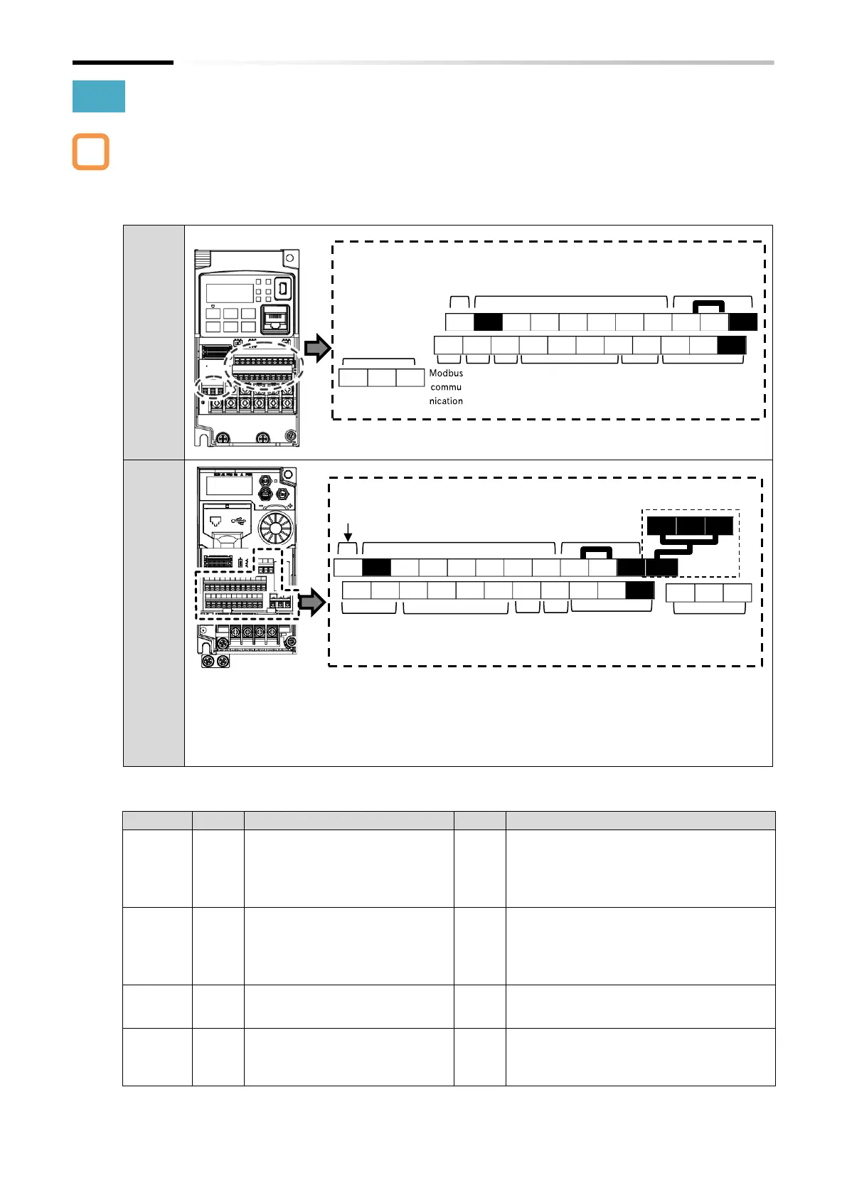
■ Comparison of control circuit terminal block arrangement
* Terminals that have been added/changed electrical characteristics/changed functions compared to
WJ200 are outlined in white.
For those whose terminal symbols only have been changed, refer to the following comparison table.
* The following terminals have the same function/electrical specifications, but the terminal symbols have
been changed. Be careful when switching wiring.
Voltage input [O] ⇒ [Ai1], Current input [OI] ⇒ [Ai2], Pulse input [EA] ⇒ [8]
Analog output [AM] ⇒ [Ao1], Pulse output [E0] ⇒ [Ao2]
■ Major changes of control circuit terminal function
By turning ON the safety function
selector switch on the control
board, input terminals 3 and 4 are
switched to the safety function STO
input terminals [GS1] and [GS2].
Safety function STO input terminals [ST1] and
[ST2] have been added as dedicated terminals.
In addition, [P24S] and [CMS] have been added
as dedicated power supply for functional safety.
Refer to "14.1 Using the Safety Function STO
(Safe Torque Off)" for more information.
By turning ON the EDM function
selector switch on the control
board, output terminal 11 is
switched to the EDM output
terminal.
In addition to the content shown on the left, in
case EDM function selector switch is ON, the
3rd and 4th of "Input terminal monitor [d005]"
switch to the status monitor of [ST1] and [ST2].
(Terminal functions assigned to input terminals
3 and 4 are not changed.)
Max. input frequency is 1.8 kHz.
Max. input frequency is 32 kHz.
(Other electrical characteristics are
unchanged.)
Power
supply
for input
signal
Internal 24 VDC power supply
terminal for contact input.
In addition to the content shown on the left, by
inputting an external 24 VDC power supply to
this terminal and the [L] terminal, only the
control board can be started.
Logic power
supply and
common
Analog input
and power
supply
Logic power supply
and common
Functional safety input and
power supply

 Loading...


