Drive Configuration D2 Series Servo Drive User Manual
5-34 HIWIN MIKROSYSTEM CORP.
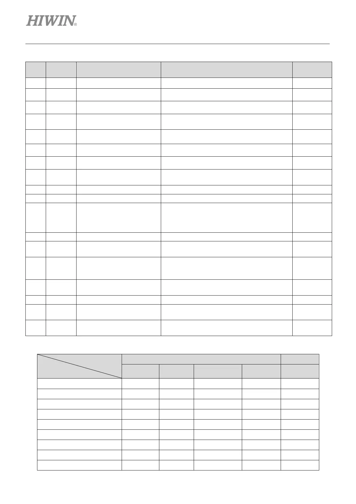
Table5.5.1.1
No.
Input function Description Trigger
1 SVN
Axis Enable Enable/Disable; the default used in I3. Level trigger
2 LL
Left Limit Switch Left hardware limit; the default used in I6. Level trigger
3 RL
Right Limit Switch Right hardware limit; the default used in I9. Level trigger
4 MAP
Home OK, start err. map
The homing completed command from the host
controller.
Edge trigger
5 RST
Reset amplifier Reset the drive. Edge trigger
6 DOG
Near home sensor Near home sensor. Level trigger
7 CE
Clear Error Clear error. Edge trigger
8 INVC
Invert V Command
Reversing the analog voltage command in the
velocity or force/torque mode.
Level trigger
Switching to secondary common gain.
Switching to secondary vpg gain.
11 ZSC
Zero Speed Clamp
Zero speed clamp. In the velocity mode, the
motor will be locked in a fixed position when the
drive receives this signal and the motor speed is
less than the set value.
Level trigger
Inhibiting the pulse command.
13 PSEL
Switch HI/LO Pulse Input
Switching between the high-speed and
low-speed pulse input channels.
Level trigger
14 EMG
Abort Motion
Emergency stop. The drive enters the
emergency stop procedure after receiving this
signal during motor motion.
Level trigger
15 MOD
Switch to secondary mode
Switching from the primary operation mode to
the secondary operation mode.
Level trigger
Starting the built-in homing procedure of drive.
17 DIV1
Electronic Gear Select (DIV1)
Selecting the electronic gear ratio in the position
mode.
Level trigger
18 DIV2
Electronic Gear Select (DIV2)
Selecting the electronic gear ratio in the position
mode.
Level trigger
Table5.5.1.2 Supported input functions for each operation mode
Operation mode
Input function
Not CoE model CoE model
Axis Enable
V V V V V
Left (-) Limit Switch
V - - V V
Right (+) Limit Switch
V - - V V
Home OK,start err. map
V V V V -
Reset amplifier
V V V V V
Near home sensor
V V V V V
Clear error
V V V V -
Invert V command
- V V - -
Switch to secondary CG
V V V V -
 Loading...

