D2 Series Servo Drive User Manual Drive Configuration
HIWIN MIKROSYSTEM CORP. 5-35
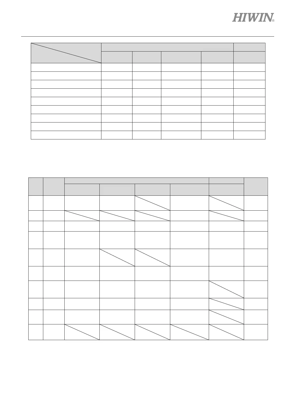
Operation mode
Input function
Not CoE model CoE model
Switch to secondary vpg
V V V V -
Zero speed clamp
- V - - -
Inhibit pulse command
V - - - -
V - - - -
Abort motion
- - - V -
Switch to secondary mode
V V V V -
Start homing
V V V V -
Select electronic gear (DIV1)
V - - - -
Select electronic gear (DIV2)
V - - - --
Note:
“V” means that the input function has this function in the corresponding mode, and can be set to I1 - I10 at will.
Table5.5.1.3 Default input setting for D2 drive
Pin Signal
Inverse
33 I1
Inhibit Pulse
Command
Zero Speed
Clamp
Start Homing
No
30 I2 Abort Motion
No
29 I3 Axis Enable Axis Enable Axis Enable Axis Enable Axis Enable No
27 I4
secondary
secondary
secondary
Switch to
secondary CG
Left (-) Limit
Switch
No
28 I5
Gear Select
Near Home
Sensor
Right (+)
Limit Switch
No
26 I6
Left (-
Limit Switch
Left (-
Limit Switch
Left (-
Limit Switch
Left (-
Limit Switch
Near Home
Sensor
No
32 I7
secondary
secondary
secondary
secondary
No
31 I8 Clear Error Clear Error Clear Error Clear Error
No
9 I9
Limit Switch
Limit Switch
Limit Switch
Limit Switch
No
8 I10*
No
Note:
Only for D2T model.
 Loading...

