D2 Series Servo Drive User Manual LCD Operation
HIWIN MIKROSYSTEM CORP. 7-13
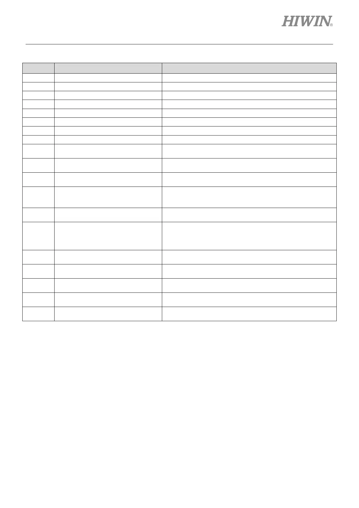
Table7.5.1 Common parameter table (set parameter based on the actual application)
LCD No. Function Description
Maximum acceleration of motor during motion
Maximum deceleration of motor during motion
Maximum velocity of motor during motion
Cutoff frequency of closed-loop filter 1
Cutoff frequency of closed-loop filter 2
The larger the value is, the higher the servo rigidity is.
081
Numerator of electronic gear ratio Numerator of electronic gear ratio (output)
Denominator of electronic gear ratio
Denominator of electronic gear ratio (input)
083
Velocity command scale (velocity
mode)
Velocity command scale; the speed corresponds to 1 V, or the
maximum speed corresponds to “Full PWM”.
085
Current command scale (torque
mode)
Current command scale; the output current corresponds to 1 V,
or the maximum current corresponds to “Full PWM”.
115
Smooth factor
The larger the value is, the smoother the motion is. (range: 1 -
500)
129
Pulse Format
1: Pulse/Direction
2: Pulse up/Pulse down (CW/CCW)
130
Inverse pulse command
0: Not inverse
1: Inverse
212
Primary operation mode
1: Position mode
2: Velocity mode
216
High speed/ low speed pulse input
switch
0: High-speed pulse input (CN6 pin 44, 45, 46, 47)
1: Low-speed pulse input (CN6 pin 1, 3, 4, 2, 5, 6)
219
Positive/negative logic of CW/CCW
pulse Switch
243
Invert of input point 3
280
Invert of CN2 brake output
340
Zero Tune Level
The higher the level is, the heavier the load is.
There are 5 levels to select: LV1 - LV5.
Note:
For the parameter name of LCD No. and its input range, refer to table 7.5.3.1.
 Loading...

