D2 Series Servo Drive User Manual Protection Function
HIWIN MIKROSYSTEM CORP. 8-7
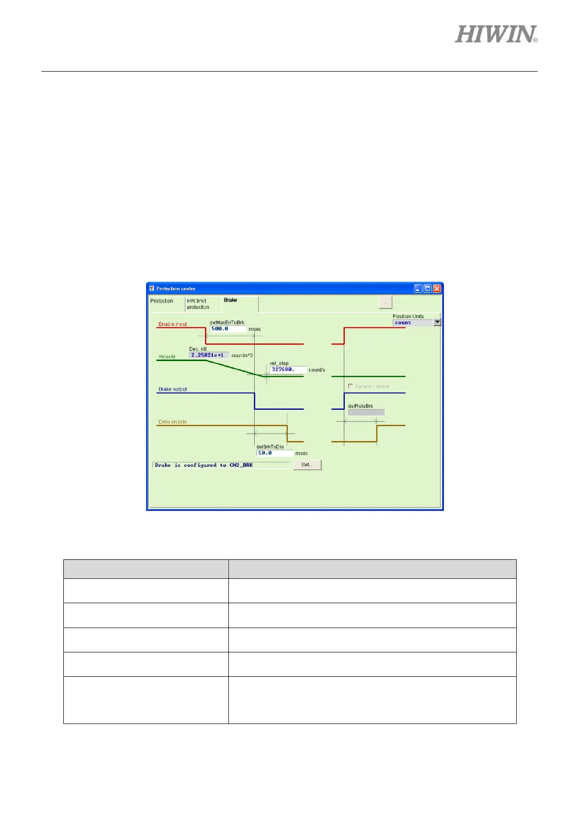
Brake configuration page for frame A - C models
The brake configuration page for frame A - C models is shown in figure 8.3.1. After the drive receives
the hardware input signal or software disable operation, it starts the following action sequence.
Step 1: When the drive receives the disable command, the brake will be started after the delay
time of starting brake (“delMaxEnToBrk”). However, if the motor speed is reduced to the
brake start speed (“vel_stop”), the brake is started first.
Step 2: Counting from the drive starting the brake, the post-stage power will be turned off after the
set brake action time (“delBrkToDis”). Its main purpose is to completely and truly execute
the brake action.
Figure8.3.1
Table8.3.1
Parameter Name Description
Delay time of starting brake
(“delMaxEnToBrk”)
The maximum time from receiving the disable command to
starting the brake.
Emergency stop deceleration (“Dec.
kill”)
The deceleration of motor brake during emergency stop. Refer to
Section 8.1.
Brake start speed (“vel_stop”)
The speed for starting the brake after receiving the disable
command.
Brake action time (“deBrkToDis”)
The delay time from starting the brake to shutting down the
post-stage current.
Delay time for the dynamic brake
relay (“delRelsBrk”)
The delay time from closing the brake to completing the
switchover of dynamic brake relay. (Frame A - C models do not
support this function. Hence, this field is anti-gray and cannot be
 Loading...

